
![grid-leak-radio-draws-the-waves-[hackaday]](https://i0.wp.com/upmytech.com/wp-content/uploads/2024/05/185477-grid-leak-radio-draws-the-waves-hackaday.png?resize=800%2C445&ssl=1)
Grid Leak Radio Draws the Waves [Hackaday]
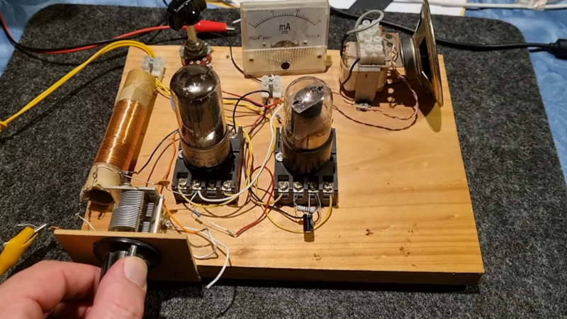
[Stephen McNamera] found a schematic for a grid leak radio online and decided to throw together a few tubes on a piece of wood and see how it worked. As you can see in the video below, it works well. The video is a bit light on details, but the web page he found the plans on also has quite a bit of explanation.
The name “grid leak detector” is due to the grid leak resistor between the grid and ground, in this case, a 2.7 megaohm resistor. The first tube does everything, including AM detection. The second tube is just an audio amplifier that drives the speaker. This demodulation method relies on the cathode to control grid conduction characteristics and was found in radios up to about the 1930s. The control grid performs the usual function but also acts as a diode with the cathode, providing demodulation. In a way, this is similar to a crystal radio but with an amplified tube diode instead of a crystal.
It looks like [Stephen] wound his own coil, and the variable capacitor looks suspiciously like it may have come from an old AM radio. The of the old screw terminal tube sockets on the wood board looks great. Breadboard indeed! What we didn’t see is where the 150 V plate voltage comes from. You hope there is a transformer somewhere and some filter capacitors. Or, perhaps he has a high-voltage supply on the bench.
While tubes are technologically passe, we still like them. Especially in old radios. Just take care around the high voltages, please.