
![ultimate-power:-lithium-ion-packs-need-some-extra-circuitry-[hackaday]](https://i0.wp.com/upmytech.com/wp-content/uploads/2024/04/177590-ultimate-power-lithium-ion-packs-need-some-extra-circuitry-hackaday-scaled.jpg?resize=800%2C445&ssl=1)
Ultimate Power: Lithium-Ion Packs Need Some Extra Circuitry [Hackaday]
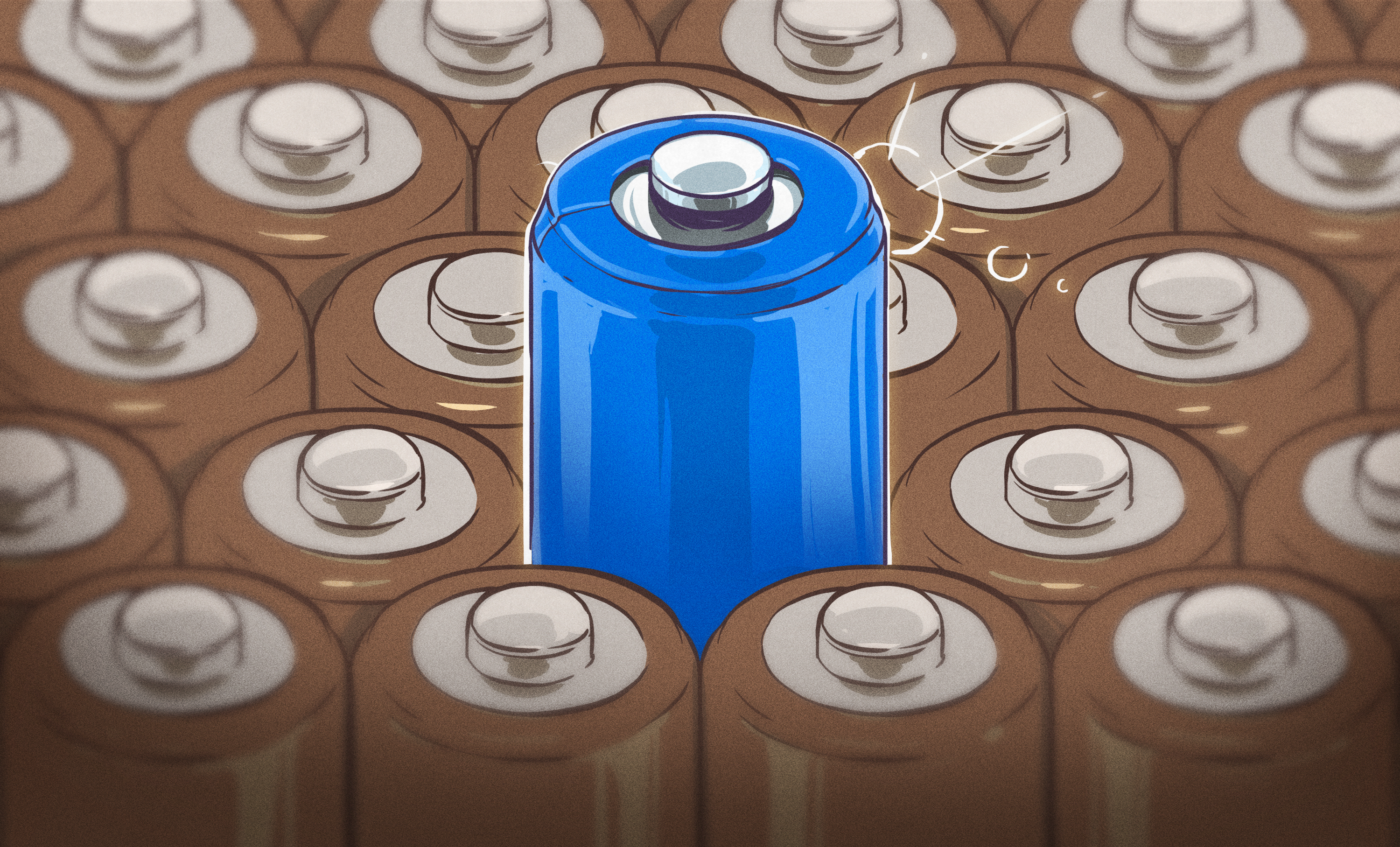
A LiIon pack might just be exactly what you need for powering a device of yours. Whether it’s a laptop, or a robot, or a custom e-scooter, a CPAP machine, there’s likely a LiIon cell configuration that would work perfectly for your needs. Last time, we talked quite a bit about the parameters you should know about when working with existing LiIon packs or building a new one – configurations, voltage notations, capacity and internal resistance, and things to watch out for if you’re just itching to put some cells together.
Now, you might be at the edge your seat, wondering what kind of configuration do you need? What target voltage would be best for your task? What’s the physical arrangement of the pack that you can afford? What are the safety considerations? And, given those, what kind of electronics do you need?
Picking The Pack Configuration
Pack configurations are well described by XsYp:X serial stages, each stage having Y cells in parallel. It’s important that every stage is the same as all the others in as many parameters as possible – unbalanced stages will bring you trouble.
Now, where do you want to fit your pack? This will determine the voltage. If you want to quickly power a device that expects 12 V, the 10.5 V to 11.1 V of a 3s config should work wonders. If your device detects undervoltage at 10.5V, however, you might want to consider adding one more stage.
How much current do you want to draw? For the cells you are using, open their spec sheet yet again, take the max current draw per cell, derate it by like 50%, and see how many cells you need to add to match your current draw. Then, add parallel cells as needed to get the capacity you desire and fit the physical footprint you’re aiming for.
The last word for section this is on safety. When working with packs that exceed 20V , you are at a higher risk of injury than with the usual low-voltage electronics. DC doesn’t shock you the way AC does, it makes your muscles contract in a way that risks you holding onto whatever is shocking you, and, it also can fry your muscles from the inside. If you’re working with ebike packs, you should seriously heed the advice of having one hand in your pocket as much as humanly possible.
Not only that, but working with LiIon packs is physically dangerous even if you don’t get shocked. At a certain pack voltage and capacity, a short-circuit can blind you, and it will easily melt your metal tools – use plastic as much as possible. If it can drive your ebike motor, it contains enough energy to do a lot of damage.
Thankfully, in the end, safety is manageable. Plus, there’s electronics that help you take care of it.
Electronics And Balancing
In terms of circuitry, you need three things for a LiIon pack – charging, protection, and balancing. So, let’s start with balancing, because balancing circuits give you some much-needed insights into LiIon pack charging requirements.
Balancing is seriously required for LiIon packs that have more than one cell in series. A LiIon charger chip by definition doesn’t monitor individual stages in the series. Over time, the stages in any pack will develop mismatches in internal resistance and capacity, if they’re not noticeably present by the moment the pack is built. During charging, this means that some of the stages might get fully charged while other stages haven’t finished charging yet – and a LiIon charger that’s only connected to the single series ground and output can’t detect that, so it will continue pumping current into the pack, which might lead to overcharging.
You have to add a balancer if you want your pack to be safe, doubly so with high stage count packs where even miniscule differences will soon be exacerbated. And triply so if you’re making your pack out of salvaged batteries, which may have mismatches that series charging would exacerbate.
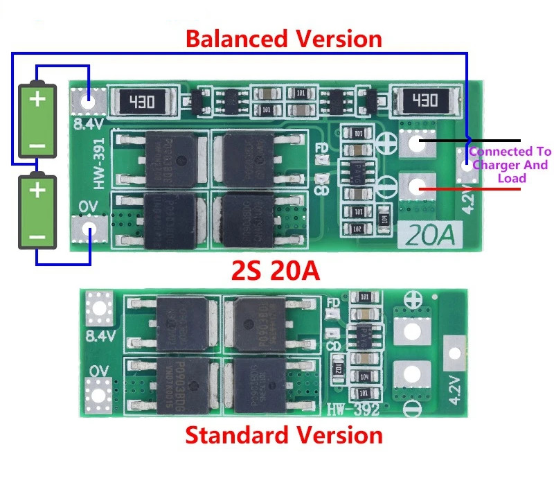
If you’re looking for a protection circuit that does balancing for you, look out for rows of SMD resistors on the board. Balancers are not a substitute for a badly built pack – they can’t dissipate all that much current; ultimately, they are safeguards that help keep a good pack from going bad, and you need them just as much as you need both the charging and protection circuits.
Charging And Protection
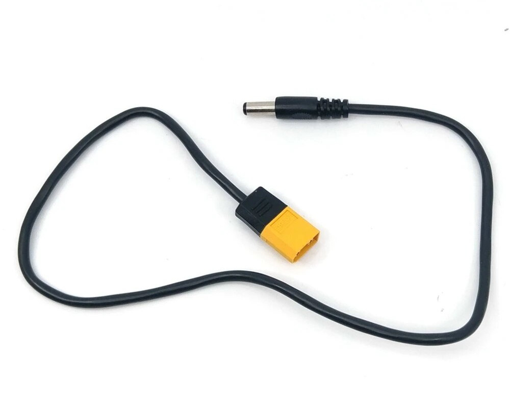
Once you move to a multi-stage pack, the classic TP4056 single-stage chargers will not work anymore, as much as I love them. Instead, get a charger chip that can handle series configurations – you can find them reasonably easily. For low-count-series and high-count-series packs, there are plenty of charging circuits on Aliexpress. For low-count-series packs, these circuits take the form of small modules, TP4056-like, just explicitly being marked “2s” or “8.4 V”.
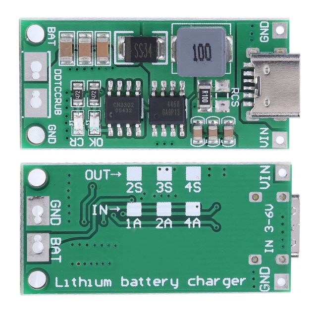
Best is if everything is under your control. You must have control over charger’s configured termination voltage, or at least know what voltage it’s set to – too high and you overcharge, which is pretty bad; too low and you undercharge, which is actually beneficial for pack health but will result in you losing out on capacity. You will likely want control over charging current, too – just like with voltage, it can be too small, but it can’t be too large.
As with the single-cell setups, there are also multi-series protection circuits that safeguard you from overcurrent and overdischarge. These aren’t meant as a substitute for proper handling, but they can protect you from accidents like short-circuits on the output or a charger going haywire; not that there can’t be a spark, but the spark’s consequences will be greatly diminished.
It’s even more convenient when the balancing circuit and overdischarge are included in one PCB. These battery management system boards (BMS) are plentiful on the market and take care of everything under one roof. Look for large SMD resistors as a good indicator that the circuit has balancing as well as overcurrent protection. These boards often lack programmable overcurrent thresholds, though, so be ready to find part numbers for extra FETs and solder them onto conveniently unpopulated footprints if you want to up the limit.
These are the basics you need to work with a multi-stage pack. Is anything unclear? Ask in the comments below – this is the kind of topic where misunderstandings are worth getting corrected early.