
![the-computers-of-voyager-[hackaday]](https://i0.wp.com/upmytech.com/wp-content/uploads/2024/05/182222-the-computers-of-voyager-hackaday-scaled.jpg?resize=800%2C445&ssl=1)
The Computers of Voyager [Hackaday]
After more than four decades in space and having traveled a combined 44 billion kilometers, it’s no secret that the Voyager spacecraft are closing in on the end of their extended interstellar mission. Battered and worn, the twin spacecraft are speeding along through the void, far outside the Sun’s influence now, their radioactive fuel decaying, their signals becoming ever fainter as the time needed to cross the chasm of space gets longer by the day.
But still, they soldier on, humanity’s furthest-flung outposts and testaments to the power of good engineering. And no small measure of good luck, too, given the number of nearly mission-ending events which have accumulated in almost half a century of travel. The number of “glitches” and “anomalies” suffered by both Voyagers seems to be on the uptick, too, contributing to the sense that someday, soon perhaps, we’ll hear no more from them.
That day has thankfully not come yet, in no small part due to the computers that the Voyager spacecraft were, in a way, designed around. Voyager was to be a mission unlike any ever undertaken, a Grand Tour of the outer planets that offered a once-in-a-lifetime chance to push science far out into the solar system. Getting the computers right was absolutely essential to delivering on that promise, a task made all the more challenging by the conditions under which they’d be required to operate, the complexity of the spacecraft they’d be running, and the torrent of data streaming through them. Forty-six years later, it’s safe to say that the designers nailed it, and it’s worth taking a look at how they pulled it off.
Volatile (Institutional) Memory
That turns out that getting to the heart of the Voyager computers, in terms of schematics and other technical documentation, wasn’t that easy. For a project with such an incredible scope and which had an outsized impact on our understanding of the outer planets and our place in the galaxy, the dearth of technical information about Voyager is hard to get your head around. Most of the easily accessible information is pretty high-level stuff; the juicy technical details are much harder to come by. This is doubly so for the computers running Voyager, many of the details of which seem to be getting lost in the sands of time.
As a case in point, I’ll offer an anecdote. As I was doing research for this story, I was looking for anything that would describe the architecture of the Flight Data System, one of the three computers aboard each spacecraft and the machine that has been the focus of the recent glitch and recovery effort aboard Voyager 1. I kept coming across a reference to a paper with a most promising title: “Design of a CMOS Processor for use in the Flight Data Subsystem of a Deep Space Probe.” I searched high and low for this paper online, but it appears not to be available anywhere but in a special collection in the library of Witchita State University, where it’s in the personal papers of a former professor who did some work for NASA.
Unfortunately, thanks to ongoing construction, the library has no access to the document right now. The difficulty I had in rounding up this potentially critical document seems to indicate a loss of institutional knowledge of the Voyager program’s history and its technical origins. That became apparent when I reached out to public affairs at Jet Propulsion Lab, where the Voyagers were built, in the hope that they might have a copy of that paper in their archives. Sadly, they don’t, and engineers on the Voyager team haven’t even heard of the paper. In fact, they’re very keen to see a copy if I ever get a hold of it, presumably to aid their job of keeping the spacecraft going.
In the absence of detailed technical documents, the original question remains: How do the computers of Voyager work? I’ll do the best I can to answer that from the existing documentation, and hopefully fill in the blanks later with any other documents I can scrape up.
Good Old TTL
As mentioned above, each Voyager contains three different computers, each of which is assigned different functions. Voyager was the first unmanned mission to include distributed computing, partly because the sheer number of tasks to be executed with precision during the high-stakes planetary fly-bys would exceed the capabilities of any single computer that could be made flyable. There was a social engineering angle to this as well, in that it kept the various engineering teams from competing for resources from a single computer.
The physical design of Voyager injected some extra complexity into attitude control. While previous deep-space vehicles had been fairly compact, Voyager bristles with long booms. Sprouting from the compact bus located behind its huge high-gain antenna are booms for the three radioisotope thermoelectric generators that power the spacecraft, a very long boom for the magnetometers, a shorter boom carrying the heavy imaging instruments, and a pair of very long antennae for the Plasma Wave Subsystem experiment. All these booms tend to wobble a bit when the thrusters fire or actuators move, complicating the calculations needed to stay on course.
The AACS is responsible for running the gyros, thrusters, attitude sensors, and actuators needed to keep Voyager oriented in space. Like the CCS, the AACS has a redundant design using TTL-based processors and 18-bit words. The same 4k of redundant plated-wire memory was used, and many instructions were shared between the two computers. To handle three-axis attitude control in a more memory-efficient manner, the AACS uses index registers to point to the same block of code multiple times.
Years of Boredom, Minutes of Terror
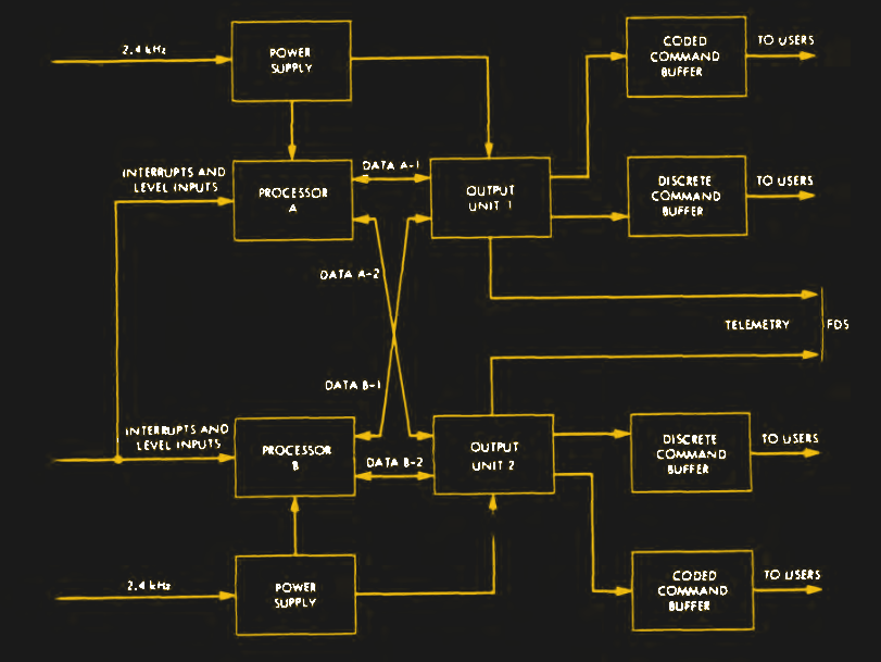
Rounding out the computers of Voyager is the Flight Data Subsystem or FDS, the culprit in the latest “glitch” on Voyager 1, which was traced to a corrupted memory location and nearly ended the extended interstellar mission. Compared with the Viking-descended CCS and AACS, the FDS was to be a completely new kind of computer, custom-made for the demands of a torrent of data from eleven scientific experiments and hundreds of engineering sensors during the high-intensity periods of planetary flybys, while not being overbuilt for the long, boring cruises between the planets.
The FDS was designed strictly to handle the data to and from the eleven separate scientific instruments on Voyager, as well as the engineering data from dozens of sensors installed around the spacecraft. The need for a dedicated data computer was apparent early on in the Voyager design process, when it became clear that the torrent of data streaming from the scientific platforms during flybys would outstrip the capabilities of any of the hard-wired data management systems used in previous deep space probes.
It was evident early in the Voyager design process that data-handling requirements would outstrip the capabilities of any of the hard-wired data management systems used in previous deep space probes. This led to an initial FDS design using the same general architecture as the CCS and AACS — dual TTL processors, 18-bit word width, and the same redundant 4k of plated-wire memory. But when the instruction time of a breadboard version of this machine was measured, it turned out to be about half the speed necessary to support peak flyby data throughput.
To double the speed, direct memory access circuits were added. This allowed data to move in and out of memory without having to go through the processor first. Further performance gains were made by switching the processor design to CMOS chips, a risky move in the early 1970s. Upping the stakes was the decision to move away from the reliable plated-wire memory to CMOS memory, which could be accessed much faster.
The speed gains came at a price, though: volatility. Unlike plated-wire memory, CMOS memory chips lose their data if the power is lost, meaning a simple power blip could potentially erase the FDS memory at the worst possible time. JPL engineers worked around this with brutal simplicity — rather than power the FDS memories from the main spacecraft power systems, they ran dedicated power lines directly back to the radioisotope thermoelectric generators (RTG) powering the craft. This means the only way to disrupt power to the CMOS memories would be a catastrophic loss of all three RTGs, in which case the mission would be over anyway.
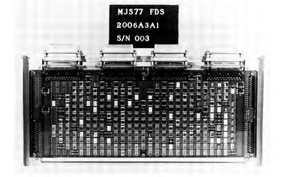
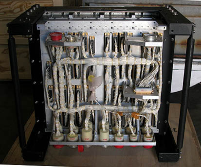
Physically, the FDS was quite compact, especially for a computer built of discrete chips in the early 1970s. Unfortunately, it’s hard to find many high-resolution photos of the flight hardware, but the machine appears to be built from eight separate cards that are attached to a card cage. Each card has a row of D-sub connectors along the top edge, which appear to be used for card-to-card connections in lieu of a backplane. A series of circular MIL-STD connectors provide connection to the spacecraft’s scientific instruments, power bus, communications, and the Data Storage Subsystem (DSS), the digital 8-track tape recorder used to buffer data during flybys.
Next Time?
Even with the relative lack of information on Voyager’s computers, there’s still a lot of territory to cover, including some of the interesting software architecture techniques used, and the details of how new software is uploaded to spacecraft that are currently almost a full light-day distant. And that’s not to mention the juicy technical details likely to be contained in a paper hidden away in some dusty box in a Kansas library. Here’s hoping that I can get my hands on that document and follow up with more details of the Voyager computers.