
![displays-we-love-hacking:-lvds-and-edp-[hackaday]](https://i0.wp.com/upmytech.com/wp-content/uploads/2024/05/182701-displays-we-love-hacking-lvds-and-edp-hackaday.jpg?resize=800%2C445&ssl=1)
Displays We Love Hacking: LVDS and eDP [Hackaday]
There are times when tiny displays no longer cut it. Whether you want to build a tablet or reuse some laptop displays, you will eventually deal with LVDS and eDP displays. To be more exact, these are displays that want you to use either LVDS or eDP signaling to send a picture.
Of the two, LVDS is the older standard for connecting displays, and eDP is the newer one. In fact, eDP has mostly replaced LVDS for things like laptop and tablet displays. Nevertheless, you will still encounter both of these in the wild, so let’s start with LVDS.
The name “LVDS” actually comes from the LVDS signaling standard (Low-Voltage Differential Signaling), which is a fairly generic data transfer standard over differential pairs, just like RS485. Using LVDS signaling for embedded display purposes is covered by a separate standard called FPD-Link, and when people say “LVDS”, what they’re actually talking about is FPD-Link. In this article, I will also use LVDS while actually talking about FPD-Link. Barely anyone uses FPD-Link except some datasheets, and I’ll use “LVDS” because that’s what people actually use. It’s just that you deserve to know the distinction so that you’re not confused when someone mentions LVDS when talking about, say, industrial machinery.

Both LVDS and eDP run at pretty high frequencies – they’re commonly used for color displays with pretty large resolutions, so speed can no longer be a constraint. eDP, as a successor technology, is a fair bit more capable, but LVDS doesn’t pull punches either – if you want to make a 1024 x 768 color LCD panel work, you will use LVDS, sometimes parallel RGB – at this point, SPI just won’t cut it. There’s a lot of overlap – and that’s because LVDS is basically parallel RGB, but serialized and put onto diffpairs. Let me show you how that happened, and why it’s cool.
Parallel RGB In A Trenchcoat
LVDS is simple enough – for a 1024 x 768 panel, you have either three or four data diffpairs, and one clock diffpair. Comparing it to parallel RGB, that’s 4-5 diffpairs (8-10 wires) instead of 18-27 single-ended wires, which greatly reduces the amount of cabling, and the differential signals make for way better noise immunity and significantly decreased electromagnetic footprint. What’s not to love?
In addition, LVDS is easy to convert to parallel RGB, and vice-versa. This is because LVDS is essentially just a transport for parallel RGB signals. All the things about parallel RGB, like porch rates, still apply – even HSYNC and VSYNC are embedded as separate bits in each “packet”.

The diagram shows it better than I could explain in text. For those who can’t see the diagram, LVDS carries those same parallel RGB signals, arranged into pseudo-packets – during six periods of the LVDS clock, each diffpair carries one defined bit of a particular pixel. You’d think that transferring a pixel now would take six to eight times as long, but since we have differential pairs, we can increase the frequency six times without consequence!
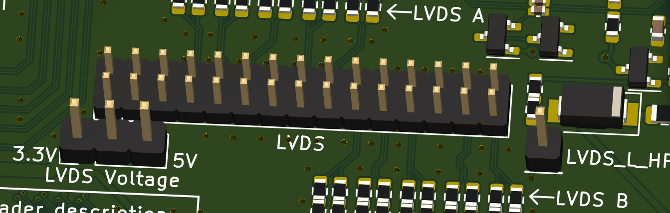
Of course, with LVDS making its way, it had to adapt to the manufacturers’ desire to raise the bar on display resolutions. You could just barely update a 1280 x 1024 display through parallel RGB – but on LVDS, we went up to 1920 x 1080. How? Simple, we put a second LVDS link in parallel, and interlaced the columns they’re responsible for. So, first link would carry pixels for columns 0, 2, 4, 6 etc., and second link would carry pixels for columns 1, 3, 5, 7 – sometimes they’re even called “odd” and “even”, and sometimes they’re called ‘A’ and ‘B’.
Let’s Hack
If you want to drive a LVDS display from a laptop or a desktop monitor, eBay and Aliexpress have $20 kits that do everything for you – driving the panel from VGA/DVI/HDMI, powering the backlight, and sometimes even a TV tuner – only give it like 12V of power. Those don’t have any jumpers, the resolution is pre-flashed, but if you’re stuck with the wrong resolution board, you can likely reflash the firmware, and maybe you can even hack on the controller itself.
There’s also a cheaper and more flexible but effortful way to drive an LVDS display – one of the MT561 “MT6820” driver boards that take VGA and output LVDS. It has about twenty combinations of “resolution x LVDS configuration” programmed into it that you can toggle with jumpers, and all you might need to do for a laptop or desktop panel is rewire the included LVDS cable according to one of the somewhat-standardized LVDS pinouts. Give it 5 V, take care of the backlight somehow, and you’ll be golden. For HDMI use, put a $3 HDMI to VGA converter into there, and that’ll be all you could need.
Most panels run at 3.3V – please switch the corresponding jumper on the driver board or you’ll kill your panel like I’ve killed some of mine. Sometimes the EDID is screwy, but nothing that you couldn’t fix with a hardcoded one, or by, again, reflashing the firmware. $20 boards are great if all you need is a specific display, but if you have multiple panels you want to play with, having a configurable board like the MT561 is a must.
The 2 mm pinheader LVDS output connector on these kinds of boards is, funnily enough, non-formally standardized itself – I’ve even seen a mass-manufactured display which used this kind of header for its internal panel connection. You can get tons of cables for this 2 mm pin header “standard”, so if you need an LVDS connector on your project and don’t want to bother with cabling, you might just want to use this one – the MXM immobilizer project I’ve recently highlighted, has such a header implemented, though it’s not yet fully tested.
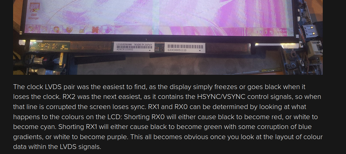
For display and laptop panels, the pinouts are also often fairly standardized – here’s an assortment of common LVDS pinouts that I’ve compiled. In more embedded displays, LVDS will often be on FPCs – there’s a few common pinouts for these as well, and therefore a few adapter boards and cables from the 2 mm standard LVDS header to an FFC connector, often with backlight drivers for the kinds of displays that need them. If your LVDS display doesn’t have a known pinout but you can probe it in a running system, you can try and short out pins to figure out which pairs correspond to which parallel RGB signals. Of course, probing it with a scope will also work, as long as your scope is fast enough.
Many SBCs, FPGAs and even industrial motherboards have LVDS outputs. If parallel RGB is what you have, you can always convert parallel RGB to LVDS, and back if you ever need to – this is how people have made LVDS HATs for a Raspberry Pi, including the one that I recently gave design review to; that one’s open-source and we’re currently doing bringup on it, check it out! I’ve seen pricey chips from Texas Instruments like SN74LVDS84A and SN65LVDS93A and there’s got to be cheaper ones, I don’t know part numbers because I haven’t had to look into it, but I trust that you can find them, and please do share them when you do!
Transition To Greatness
As you might notice, LVDS has problems. For tomorrow’s devices, LVDS is pretty limited tech shoved into a diffpair trenchcoat, and while it worked for decades, at some point the problems became too much. For instance, if you’ve wired a LVDS display up and found the colors to be wildly off, you’ll discover that there’s at least two ways to put RGB bits into a LVDS link for the same configuration, and it might be that your display expects a different one than your transmitter. Also, LVDS doesn’t have any mechanism for discovering the panel’s parameters – EDID can be used for LVDS panels, but is not required by any means and is hardly ever used in reality. Lack of link training means that running a LVDS link at higher speeds quickly becomes tricky. Last but not least, high resolutions of today require a lot of diffpairs.
At some point, we had to let LVDS go, and for most purposes where LVDS used to reign supreme, embedded DisplayPort (eDP) took hold. In laptop space, this happened about 2012-2014, with many laptops gradually switching from LVDS to eDP and some having connectors for both. eDP is a version of DisplayPort designed to be the successor for LVDS, which brings a good number of advantages by rethinking the way we send data to displays. It matters that you know about LVDS because you still might encounter it today, but for today’s purposes, eDP is where it’s at.
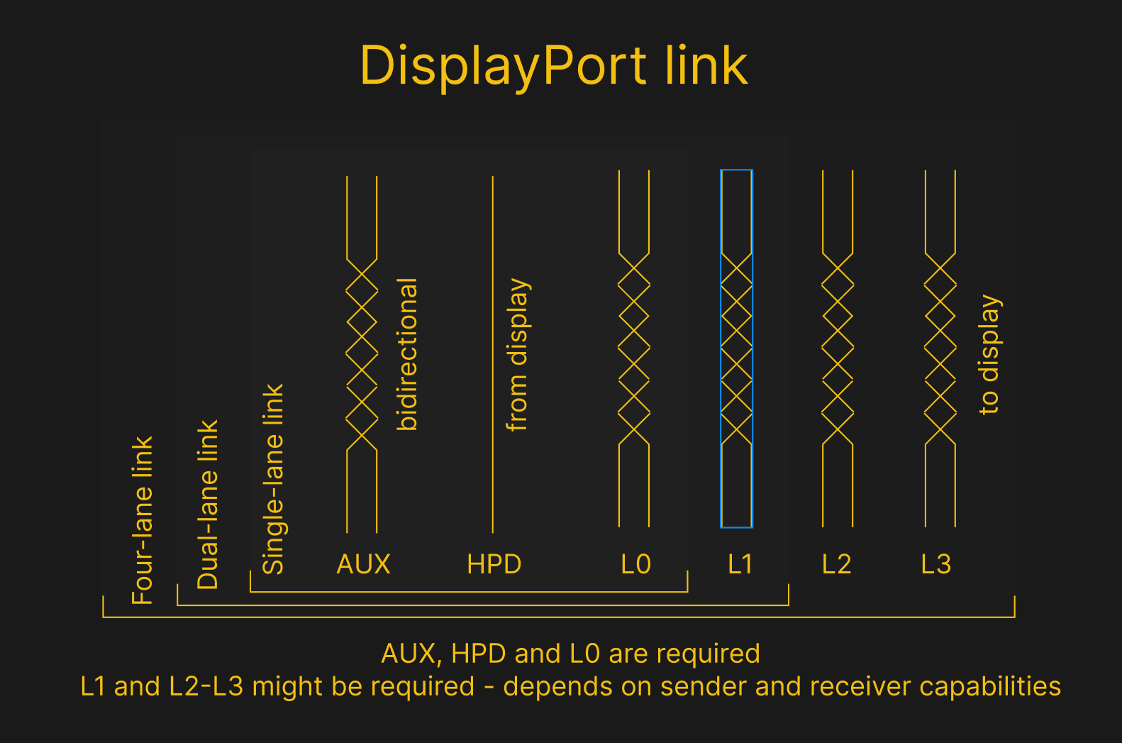
What LVDS needs ten diffpairs for, eDP can achieve with three – in fact, an eDP connection for an average 720P panel only needs two diffpairs (AUX and L0), where LVDS needs four-five. This comes at a cost of increasing layout requirements, but modern PCB technologies, connectors and wiring don’t struggle with that. eDP has a sideband channel for automatic discovery of displays, link training, and display parameter adjustments – which helps make it all that more flexible. For many purposes, eDP is indistinguishable from desktop DisplayPort, which makes it easy to find – if your system has a DisplayPort connection, it can drive an eDP panel. Let’s go through what makes eDP great and how it achieves that greatness.

I’ve talked about DisplayPort extensively in an introduction article, but I’ll recap. DP (and, subsequently, eDP) uses packets to transfer pixels data, as opposed to every widely available video interface before it (yes, even HDMI), and the packets help rid of a lot of cruft. It also removes a few base DisplayPort requirements to make eDP more embedded-friendly – for instance, better support for 1-lane and 2-lane links as opposed to mandatory 4-lane connections, as well as dropping the requirement the audio channel. Despite that, eDP is still fundamentally compatible with DisplayPort transmitters – I’ve heard of a few cases where there was incompatibility, but it was more of a “behaviour of a specific panel” kind of thing.
With DisplayPort, you can achieve way faster speeds and get more features while using less diffpairs than LVDS, and it’s also a reasonably open, straightforward to implement and easy to find standard. Sure, with eDP, the display panels themselves have to be smarter, but that’s not much of a tradeoff considering that electronics are getting more and more compact! The advancement of compact microcoax cabling into consumer electronics has also helped – in a typical eDP cable, every wire is a microcoax line that is individually shielded, so the wires don’t even have to be twisted or shielded, and there’s a ground return channel for every line.
The DisplayPort Greatness, Embedded
Now, about eDP hacking! eDP panel reuse is very similar, except you can also use desktop- and USB-C-obtained DisplayPort links to wire up a panel to your board of choice, and seamless parallel RGB conversion is no longer a thing – you need a controller chip. If you want to convert HDMI or VGA to eDP, there’s, again, controller boards, some configurable but most are pre-flashed. As a rule, a HDMI to eDP controller board with 1080p panel firmware will work with all 1080p screens – but I’ve encountered exceptions, which are not unlikely to be due to things like inadequate link training. Given how well eDP tends to work outside of these controller boards, I can’t help but blame the controller firmware writers on this one – I’ve had some controller boards which work wonders with many chips, and other boards which only function for one kind of panel. Again, the firmware is typically (even if not always) on an external SPI-connected flash chip, you can reflash it or hack on it – it’s all 8051, always has been.
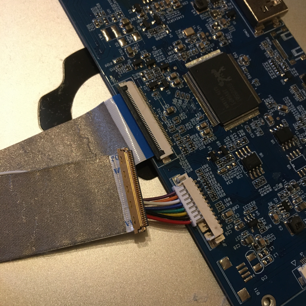
The controller boards also bring us somewhat hackable cabling – pass-through FFCs with either a 30-pin or 40-pin IPEX connector on one end, perfectly suited for hacker-friendly eDP use. They’re not noise-proof in the slightest, but if you want an eDP connector, putting a 30-pin FFC connector on your board is a good substitute in a pinch. If you want a smaller EMC footprint, better noise immunity, or don’t want to deal with a flat cable in your build, you can just get a cable that’s a microcoax assembly and put the corresponding connector on your board – more expensive, sure, but you can expect it to be reliable and slim.
This article is an explainer on LVDS and eDP, but it’s also a story about how parallel RGB became reborn into LVDS and powered our laptops and desktop monitors for two decades, and when LVDS became too much to bear, eDP took hold. On your journeys, you might encounter both of these, and I hope that now you know about all the options that can help you.
If you’d like to know more about embedded DisplayPort hacking, I’ve done an article about that in the DisplayPort series. And, a new article is incoming, with heaps of examples and references for DisplayPort wireup – stay tuned!
[Featured image: “Colours” by Lennart Tange]