
![what’s-new-in-3d-scanning?-all-in-one-scanning-is-nice-[hackaday]](https://i0.wp.com/upmytech.com/wp-content/uploads/2024/08/207865-whats-new-in-3d-scanning-all-in-one-scanning-is-nice-hackaday.jpg?resize=800%2C445&ssl=1)
What’s New in 3D Scanning? All-In-One Scanning is Nice [Hackaday]
3D scanning is important because the ability to digitize awkward or troublesome shapes from the real world can really hit the spot. One can reconstruct objects by drawing them up in CAD, but when there isn’t a right angle or a flat plane in sight, calipers and an eyeball just doesn’t cut it.
Scanning an object can create a digital copy, aid in reverse engineering, or help ensure a custom fit to something. The catch is making sure that scanning fits one’s needs, and isn’t more work than it’s worth.
I’ve previously written about what to expect from 3D scanning and how to work with it. Some things have changed and others have not, but 3D scanning’s possibilities remain only as good as the quality and ease of the scans themselves. Let’s see what’s new in this area.
All-in-One Handheld Scanning
3D scanner manufacturer Revopoint offered to provide me with a test unit of a relatively new scanner, which I accepted since it offered a good way to see what has changed in this area.
The MIRACO is a self-contained handheld 3D scanner that, unlike most other hobby and prosumer options, has no need to be tethered to a computer. The computer is essentially embedded with the scanner as a single unit with a touchscreen. Scans can be previewed and processed right on the device.
Being completely un-tethered is useful in more ways than one. Most tethered scanners require bringing the object to the scanner, but a completely self-contained unit like the MIRACO makes it easier to bring the scanner to the subject. Scanning becomes more convenient and flexible, and because it processes scans on-board, one can review and adjust or re-scan right on the spot. This is more than just convenience. Taking good 3D scans is a skill, and rapid feedback makes practice and experimentation more accessible.
Features
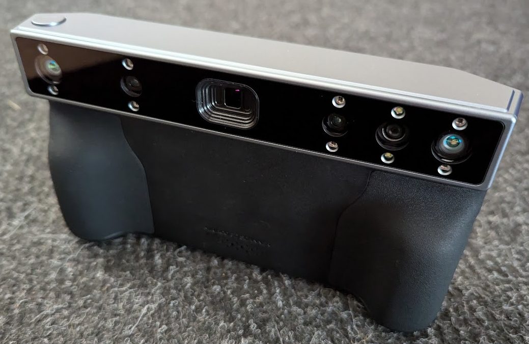
The MIRACO resembles a chunky digital camera with an array of sensors at the front and a large touchscreen on the back. As a nice touch, the screen can be flipped out to let the scanner be used in “selfie” mode.
At its core, the MIRACO is a quad-camera IR structured light sensor. A pattern of infrared light is projected, and based on how this known pattern is observed by cameras to land on an object, the object’s topology can be inferred and eventually turned into a 3D model.
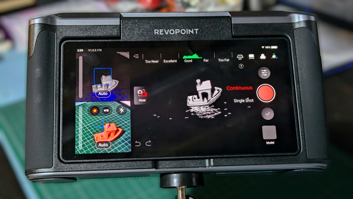
This method is sensitive to both exposure and focal distance, but the MIRACO tries to cover these bases by offering near and far focal modes (for small and large objects, respectively) as well as a live preview from which the user can judge scan conditions on the fly. Since the human eye cannot see IR, and most of us lack an intuitive sense of how IR interacts with different materials, this last feature is especially handy.
It’s worth mentioning that the models generated by the MIRACO’s scans are 1:1 with real-world dimensions. Having 3D models scaled to match the object they came from is stupendously useful when it comes to anything related to objects fitting into or around other objects.
Limitations
3D scanning is in general still not a foolproof, point-and-shoot process. As with photography, there is both a skill and an art to getting the best results. An operator has to do their part to give the sensor a good view of everything it needs.
Conditions Have to be Right
- One needs to scan in an environment that is conducive to good results. Some materials and objects scan easier than others.
- The scanner is particularly picky about focal length and exposure settings, and can be sensitive to IR interference and reflections. In terms of scanning with the MIRACO, this means the projected IR should be bright enough to illuminate the object fully while not being so bright that it washes out important features.
- IR isn’t visible, so this isn’t easy to grasp intuitively. Happily, there’s a live display on the screen for both exposure and focus distance. This guides a user to stay within the sweet spots when scanning. Better results come easily with a bit of experience.
Scans Are Only as Good as the Weakest Link
-
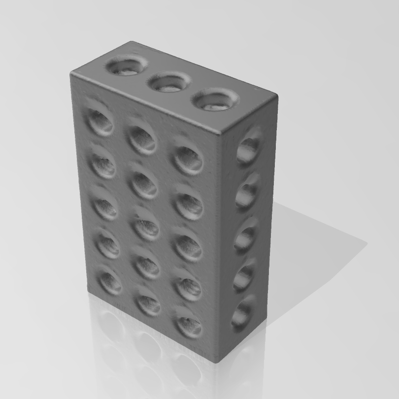
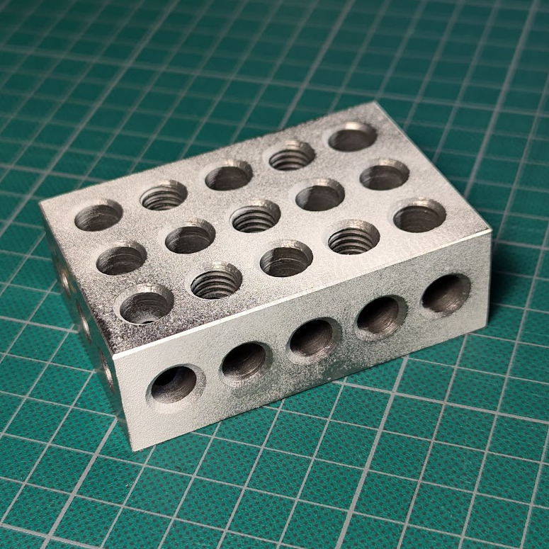
The scanner only models what it can see. The holes in this 1-2-3 block for example are incomplete. There is a long chain of processes to go from raw sensor data to finished 3D model, and plenty of opportunity for scans to end up less than ideal along the way.
- 3D scanners like to boast about scan quality with numbers like “0.02 mm accuracy”, but keep in mind that such numbers are best cases from the raw sensor itself.
- When it comes right down to it, a generated model can only be as good as the underlying point cloud. The point cloud is only as good as the sensor data, and the quality of the sensor data is limited by the object and its environment.
- Also, a scanner can only scan what it can see. If an internal void or channel isn’t visible from the scanner’s perspective, it won’t be captured in a scan.
It is not hard to get useful results with a little practice, but no one will be pointing a box and pressing a button to effortlessly receive perfect scans down to the last fraction of a millimeter anytime soon. Have realistic expectations about what is achievable.
Basic Workflow of a 3D Scan
Here is the basic process for scanning an object with the MIRACO that should give a good idea of what is involved.
Job Setup and Scan
A scan begins by configuring the scanner via touchscreen with some basics like choosing Near or Far mode, object type, and whether to track features or markers. Because the scanner only sees a portion of the object at a time, the software stitches together many images from different angles to build the point cloud that is the foundation for everything else. Alignment of these partial scans is done on the fly either by tracking features (unique shapes on the object) or markers (reflective dots that can be applied as stickers, or printed on a mat.)
If an object is excessively glossy or reflective or otherwise difficult for the scanner to see properly, treat it with a surface coating for better results. One option is dusting it with talcum powder, another is a purpose-made 3D scanning spray like AESUB offers.
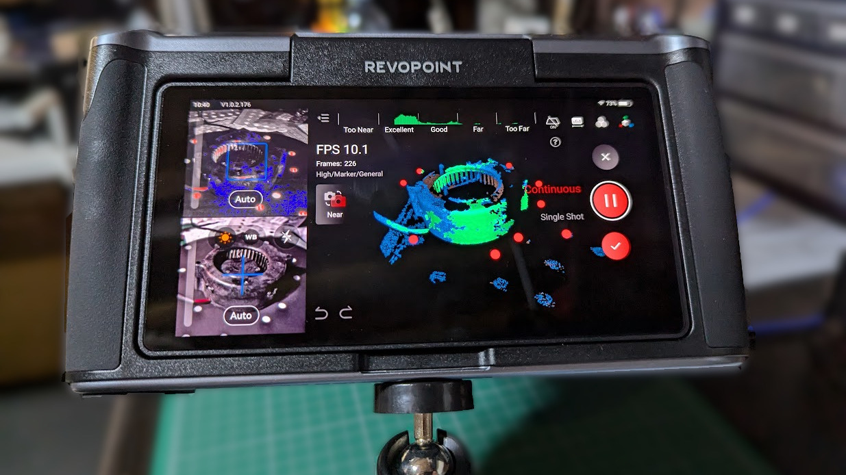
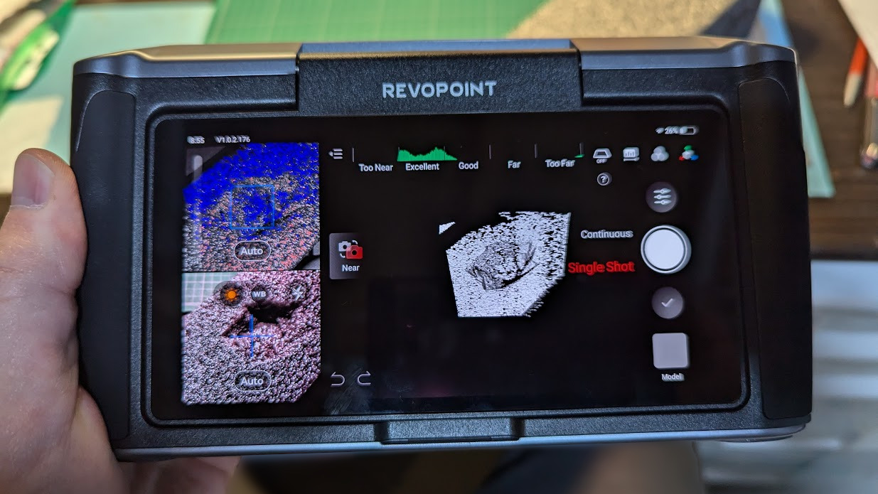
With object and scanner ready, The MIRACO is pointed like a camera and moved around the object (or the object spun on a turntable) while trying to stay an optimum distance away for best results. The screen gives feedback on this process, including a live display as the device stitches scans together.
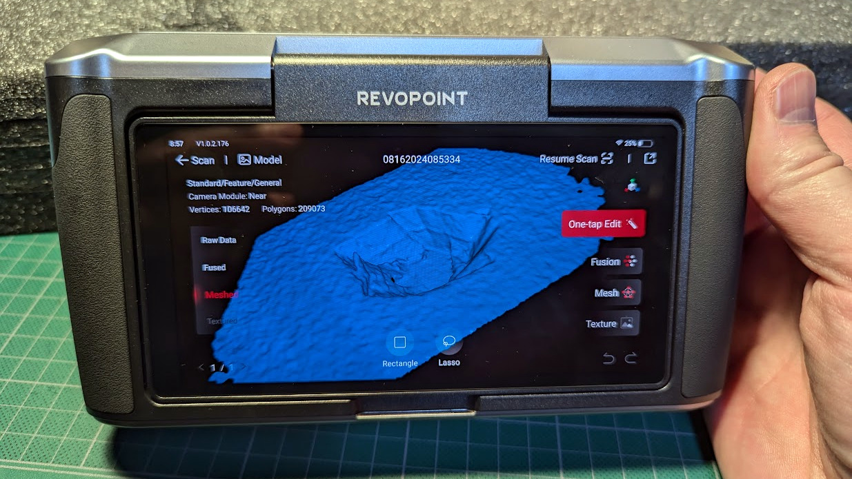
Processing Results
Results can be viewed on the device, and generally speaking, if the scan quality is good then the automatic one-click model processing will easily generate a reasonable 3D model. If there’s a problem, one can continue scanning or try again.
Scans can be exported in a variety of formats via USB or over Wi-Fi. If Revopoint’s Revo Scan software is installed, additional editing and processing options are available such as merging multiple separate scans of an object or fine-tuning processing steps.
Using The Resulting Model
The resulting 3D model (a mesh output like .STL, .3MF, or .OBJ) may require additional processing or editing depending on what one wishes to do with it. A mesh editing program like Blender is full-featured, but Microsoft’s 3D Builder is pretty handy for many common tasks when it comes to editing and handling meshes. Most slicer software for 3D printers can handle basic things as well.
Example Scans and Projects
Here are a few scans and prints I did to illustrate the sort of results you should expect with a tool like this. Each of these highlights an important aspect of scanning from the context of part design and 3D printing. The MIRACO is also capable of scanning large objects, though I focus on smaller ones here.
Scanning a Part, Designing a Socket for that Part
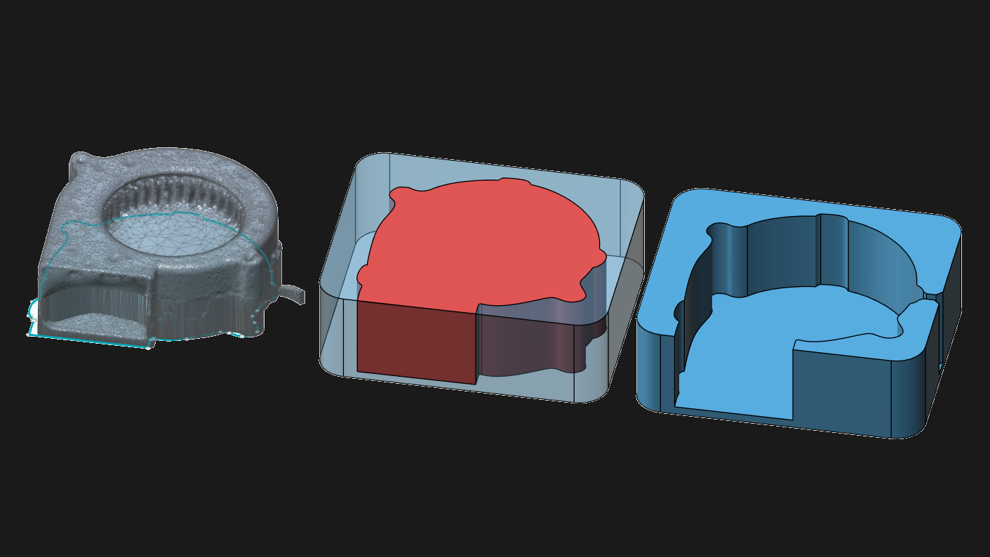
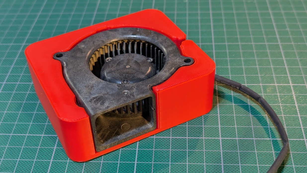
This first example demonstrates scanning an object (in this case, a fan) in order to design a socket in another piece that will fit it perfectly.
To do this, I scanned the fan (including attached cable) then manually traced its vertical footprint in CAD. This created a sort of cutout object I could use to make a socket. Objects with more complex shapes can be cut into slices, and each slice traced individually.
I’d like to point out that because the scan is being used as a reference for a CAD sketch, imperfect or otherwise incomplete scans can still be perfectly serviceable as long as the right parts of the object are intact.
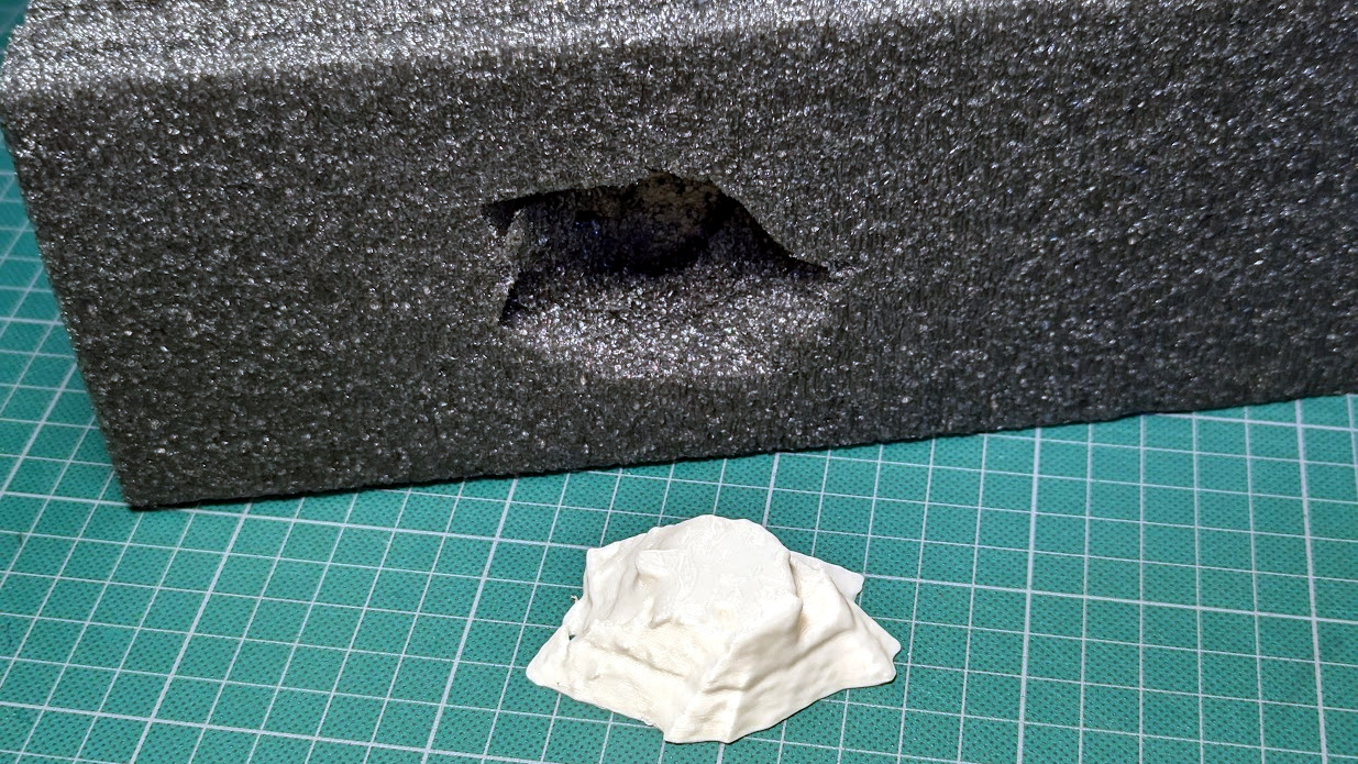
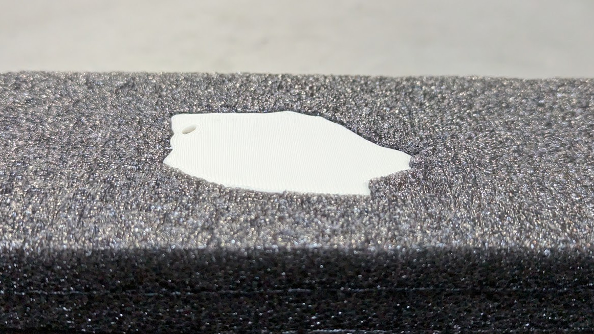
Scanning a Hole and Printing a Plug
This is a great way to show the different possibilities and features in action, such as the fact that scans are 1:1 with their real-world subject.
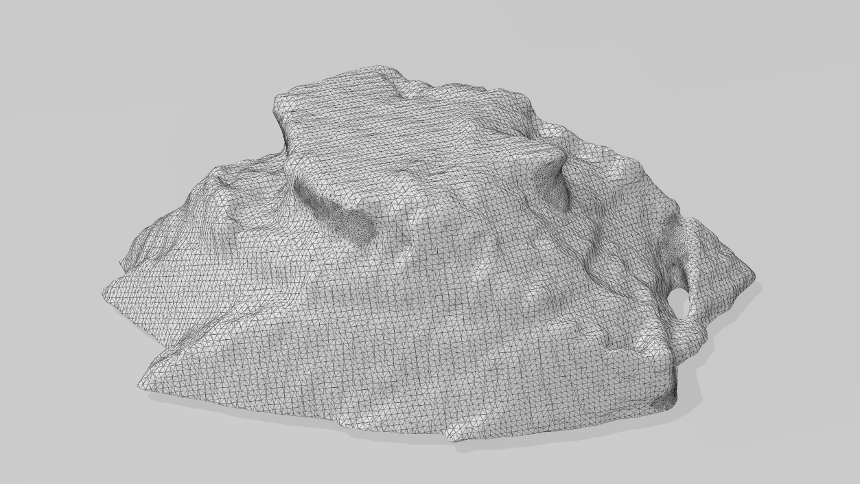
I roughly chopped a hole out of a chunk of packing foam, scanned the hole, then 3D printed a model of the hole to use as a plug. It fits perfectly, and its shape even accurately captured small details I hadn’t noticed.
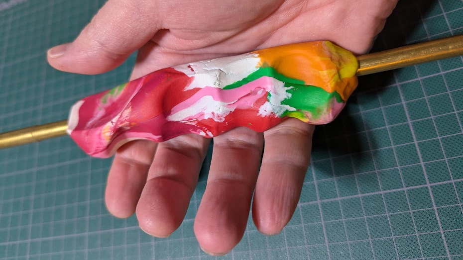
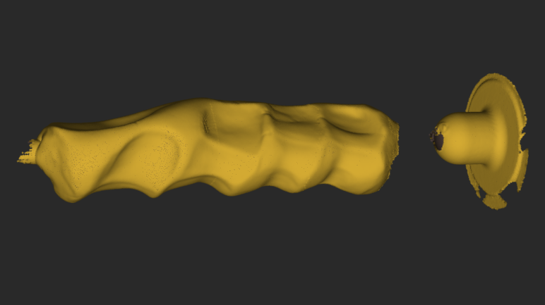
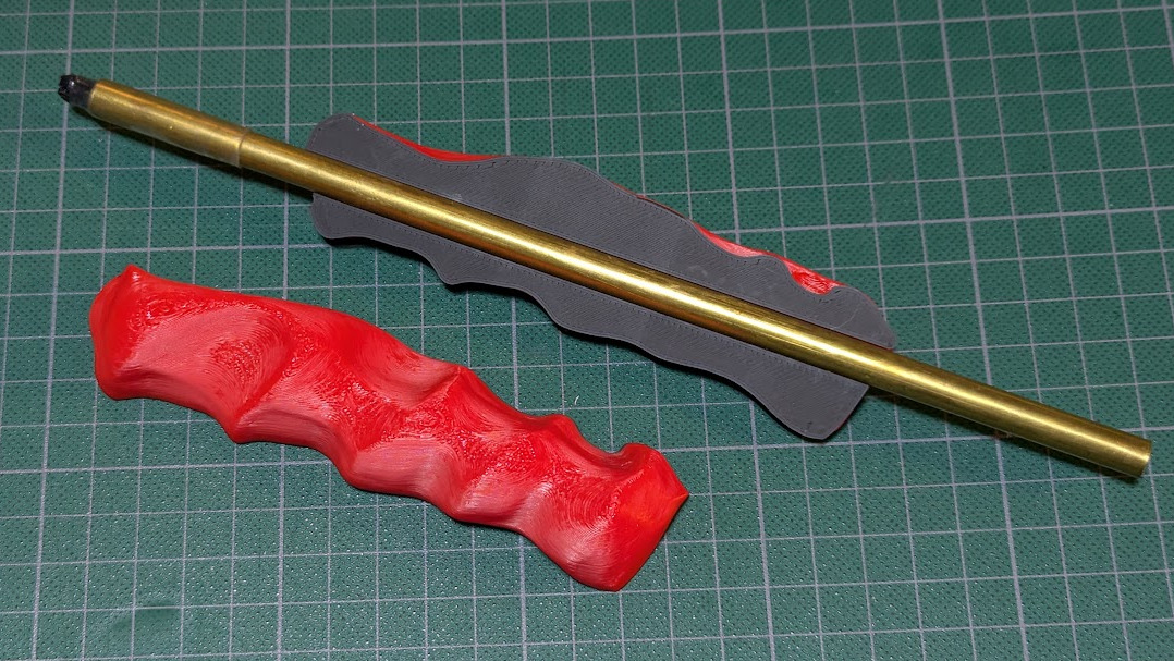
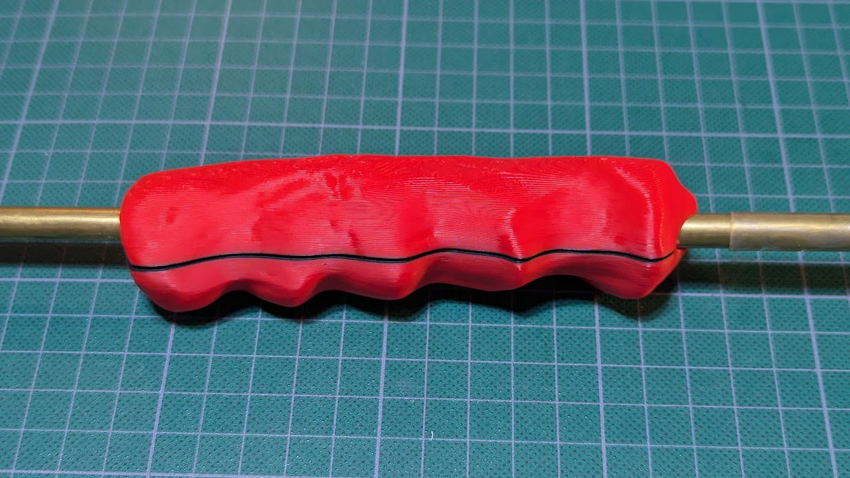
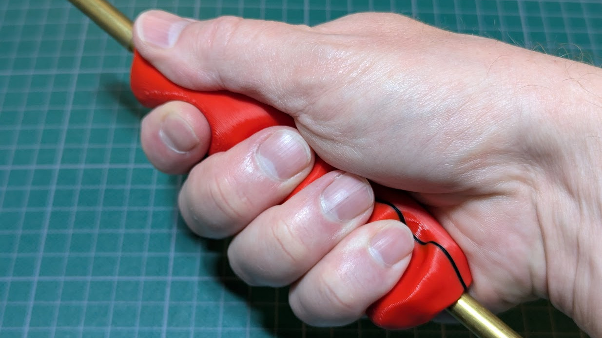
Custom Ergonomic Grip
3D scanning is a great way to capture objects with complex shapes that cannot be modeled by calipers and squinted eyeballs alone. Wearables and handhelds are one example, and here I demonstrate creating a custom, ergonomic grip.
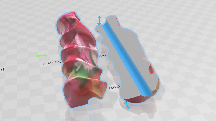
I use modeling clay to create a custom hand grip, then scan the result. The scan is easily edited in terms of separating into halves, making a central hole for mounting, and 3D printing the result.
Note that I scanned this object in color (which the MIRACO is capable of) but the color scan serves no real function here other than being more visual.
Remaining Challenges
So what’s not new in 3D scanning? The tools and software are certainly better and easier to use, but some things remain challenging.
Some Objects Scan Better Than Others
Scanning is still fussy about how a subject is framed and shot, as well as how reflective it is or isn’t. Taking these into account is part of getting good results.
3D Scanners Output Meshes, Not CAD Models
I’ve explained before how meshes are fundamentally different from what one is usually working with in a CAD program when designing physical parts. “Widen this hole by 0.5 mm” or “increase this angle by 5 degrees” simply aren’t the kind of edits one easily does with a mesh.
Converting a Mesh to a CAD Format Remains Imperfect
Turning an .stl into an .stp (for example) still doesn’t have great options. Tools exist, but the good ones are mostly the domain of non-free CAD suites; the kind with hefty price tags on annual licenses.
The good news is that meshes not only 3D print just fine, they also work easily with basic Boolean operations (merge, subtract, intersect) and can be used as references when modeling a part. Having a scan that is scaled 1:1 to real-world dimensions is a big help.
What’s Your Experience?
3D scanning is still a process that depends on and benefits greatly from a skilled operator, but it’s getting easier to use and easier to experiment with.
Photogrammetry is still an accessible way to do 3D scanning that requires no special hardware, but it lacks immediate feedback, and the resulting 3D model will not be a 1:1 match to real-world dimensions.
Have you found 3D scanning useful for something? What was the best part? The worst? We’d love to hear about it, so share your experience in the comments.