
![usb-c-for-hackers:-build-your-own-psu-[hackaday]](https://i0.wp.com/upmytech.com/wp-content/uploads/2023/10/146929-usb-c-for-hackers-build-your-own-psu-hackaday-scaled.jpg?resize=800%2C445&ssl=1)
USB-C For Hackers: Build Your Own PSU [Hackaday]

What if you wanted to build your own USB-C PSU? Good news – it’s easy enough! If you ever wanted to retrofit a decent DC PSU of yours to the USB-C standard, say, you got a Lenovo/HP/Dell 19V-20V charger brick and you’ve ever wished it were USB-C, today is the day when we do exactly that. To be fair, we will cheat a bit – but only a tiny bit, we won’t be deviating too much from the specification! And, to begin with, I’ll show you some exceptionally easy ways that you can turn your DC PSU into a USB-C compatible one, with a simple module or a few.
Now, for that, a PSU offers a list of profiles, and we looked into those profiles in the Replying PD article – each profile is four bytes that contain information about the profile voltage, maximum current that the device may draw at that voltage, and a few other details. For a PSU to be USB-C compliant, the USB-C specification says that, in addition to 5 V, you may also offer 9 V, 15 V, and 20 V.
Also, the specification says that if a PSU supports certain in-spec voltage like 15 V, it’s also required by the spec to offer all of the spec-defined voltages below the maximum one – for 15 V, that also requires supporting 9 V. Both of these are UX requirements, as opposed to technical requirements – it’s easier for device and PSU manufacturers to work with a small set of pre-defined voltages that majority of the chargers will support, but in reality, you can actually offer any voltage you want in the PSU advertisement; at worst, a device is going to refuse and contend with slowly charging from the 5 V output that you’re required to produce.
I’d like to walk you through how off-the-shelf USB-C PSUs work, all of the options you can use to to create one, and then, let’s build our own USB-C PSU from scratch!
All The Off-The-Shelf Options
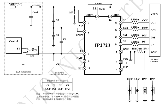
These few caveats are already baked into USB-C PSUs. After all, with modern controller chips, it doesn’t take much to add USB-C output support to a generic PSU during manufacturing – all you really need is to use a PD controller IC that ties into the PSU’s feedback line, adds an inline current sensor, and controls a MOSFET to switch the power on and off, and this IC also takes care of the USB-C rules and regulations. With the FB pin under its control, the PD controller takes over the PSU’s output voltage regulation process and make the PSU output any voltage it could ever want, within reason.
As a benefit, by adjusting the PSUs feedback line, you can get all the intermediate voltages you could want – so, PSU makers don’t have to limit themselves to weird static voltages like 7.5 V and 11 V anymore. This last part also means that features like PPS (variable voltage and CC/CV) support are not about the way your PSU is built specifically, but merely about whether the PD controller IC in your PSU supports it – and the new generations of PSU-side PD controller ICs tend to support PPS by default, which means that finding a USB-C charger with PPS is soon going to become trivial, if it already isn’t.
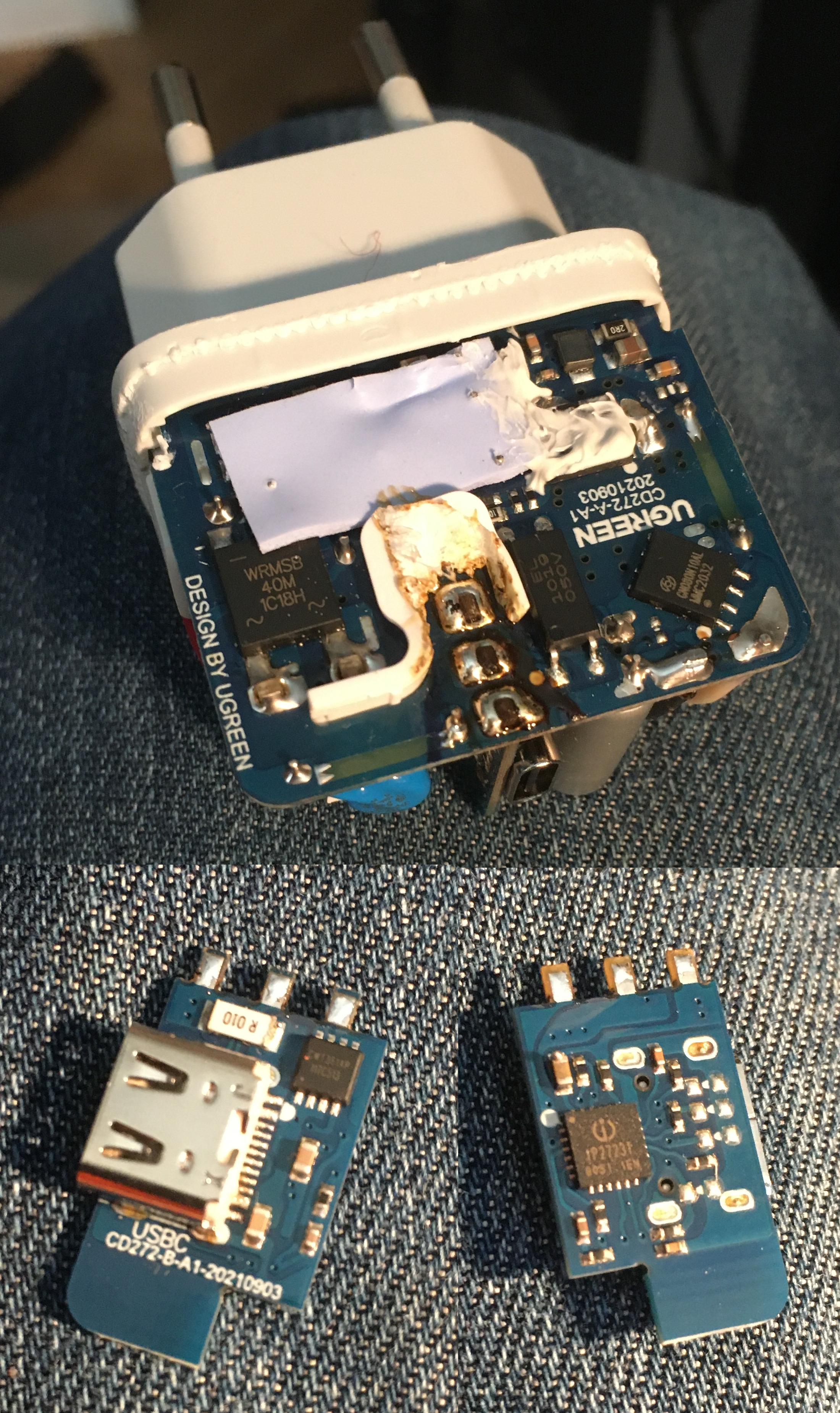
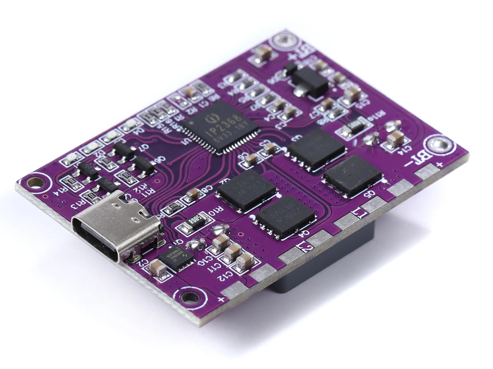
Nowadays, there’s a number of such ICs on the market that you can use to seamlessly convert an old or new PSU design to USB-C, just by tapping into the feedback line inside the PSU, and you can get these ICs from Eastern and Western manufacturers alike. If you have an already-working DC PSU, however, you don’t have to disassemble it and solder a USB-C PSU module into the feedback input – there are more and modules on the market that take a DC input, have a small PD controller chip, and also a buck (or even buck/boost!) converter to produce all the USB-C voltages a device could need!
If you want keywords, I could find a fair few by using “PD charger module” and then checking the pictures for visible inductors. One small exception is LiIon chargers with USB-C PD input, but it should be easy to filter these out by checking the title for any Lithium-Ion chemistry keyword references.
Both the lighter adapter and the Aliexpress options are very technologically similar to the native USB-C PSU option – you get a buck/boost converter with the same IC tapping into its FB signal, or even an all-things-contained IC that does everything for you if you just give it an inductor and a few other parts. But if feeding either 5 V or 20 V is all there is to your usecase, you can get even simpler than that!
Specification Versus Reality
If you think that your 20 V PSU should be able to simply put 20 V onto USB-C, or you want to avoid conversion inefficiencies, maybe you’d like to try to make the most straightforward PSU possible, there’s absolutely a way to do it all! In a USB-C PSU, you can technically limit yourself to 5 V and 20 V outputs, switching between them using FETs: if a device can’t work with a 20 V profile, it won’t request it, so you might not be able to charge your Nintendo Switch or smartphone at higher than 5 V, but it will be just right for a laptop. You can even offer custom voltages and leave it it up to devices to accept those! For instance, 12 V is not a voltage defined in the USB-C specifications, but half of PSUs on the market offer it nevertheless, purely because a large amount of the PD PSU controller ICs out there have 12 V programmed into them as an option. So, 12 V is more of a USB-C tradition than an actual profile, and yet devices work with it – it’s a mainstay on trigger boards, too!

Let’s build a DC PSU to USB-C PSU adapter that talks to USB-C devices and can offer its high voltage passthrough when they request it – efficient, hackable, and a learning opportunity. For that, you need this adapter to provide 5 V first, at a certain amount of current – but even that amount of current can be custom, you could theoretically offer 500 mA at 5 V and be done with it, so you don’t need to use too powerful of a buck regulator. I’m going to use an AP63200 switching regulator, which can produce up to 5 V / 2 A from a 20 V source.
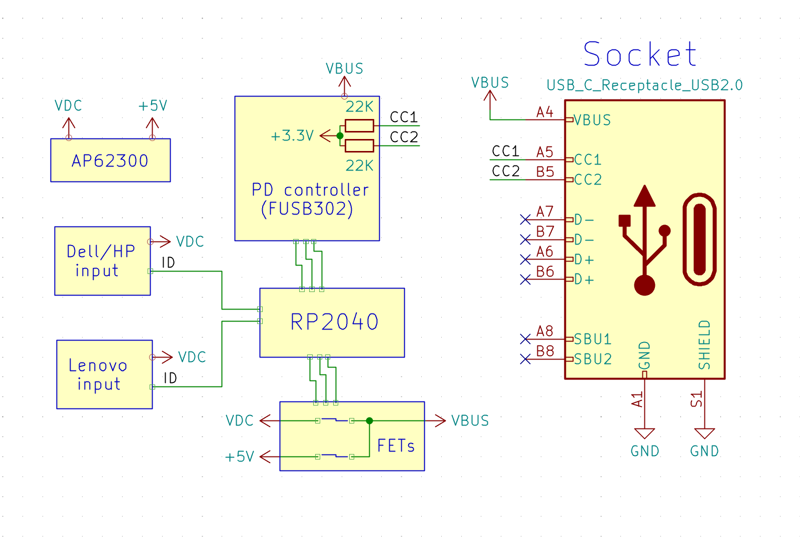
You also want to make sure your 20 V is reasonably noise-free, as the USB-C standard has some requirements for that. I’m going to be using OEM laptop PSUs from HP/Dell/ Lenovo, which tend to be of good quality compared to off-brand copies. Also, you want to know your PSU’s current capability – USB-C devices have a responsibility to monitor and temper their current consumption, so a typical laptop charger will only consume 5 A if your PSU says it can deliver 5 A, but if you tell your device you can deliver 5 A when your 20 V PSU can’t, your device might happily try and draw 5 A, triggering the overcurrent protection in the PSU. Thankfully, with the HP/Dell/Lenovo triad, their chargers have a mechanism to communicate current consumption, and with a few extra GPIOs and ADCs, I can just use that to check what kind of current we can provide!
Fast, Exact Transitions
The FET arrangement we need to switch between 5 V and 20 V output implies some requirements – you don’t want 20 V backfeeding into 5 V, and you also want the FETs to handle 3 A – 5 A of current through without breaking a sweat. When switching between 20 V and 5 V, you also want to make sure that 5 V power is not interrupted – the transition between 5 V and 20 V has to be reasonably smooth, without losing VCC. I’m going to use SI4909DY FETs, a pair of P-FETs in comfortable SO8, one pair for 5 V use and one for 20 V use, trying and keep the FETs gate voltage at about 10 V max, since that’s where the datasheet says these FETs work optimally. Let’s go through the wiring, which has some nuances – mind you, you can’t afford to feed 20 V into your 5 V rail!


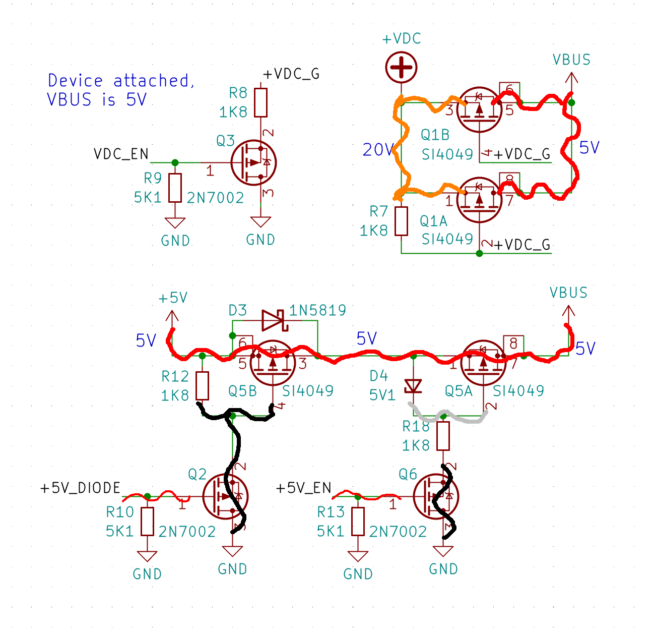
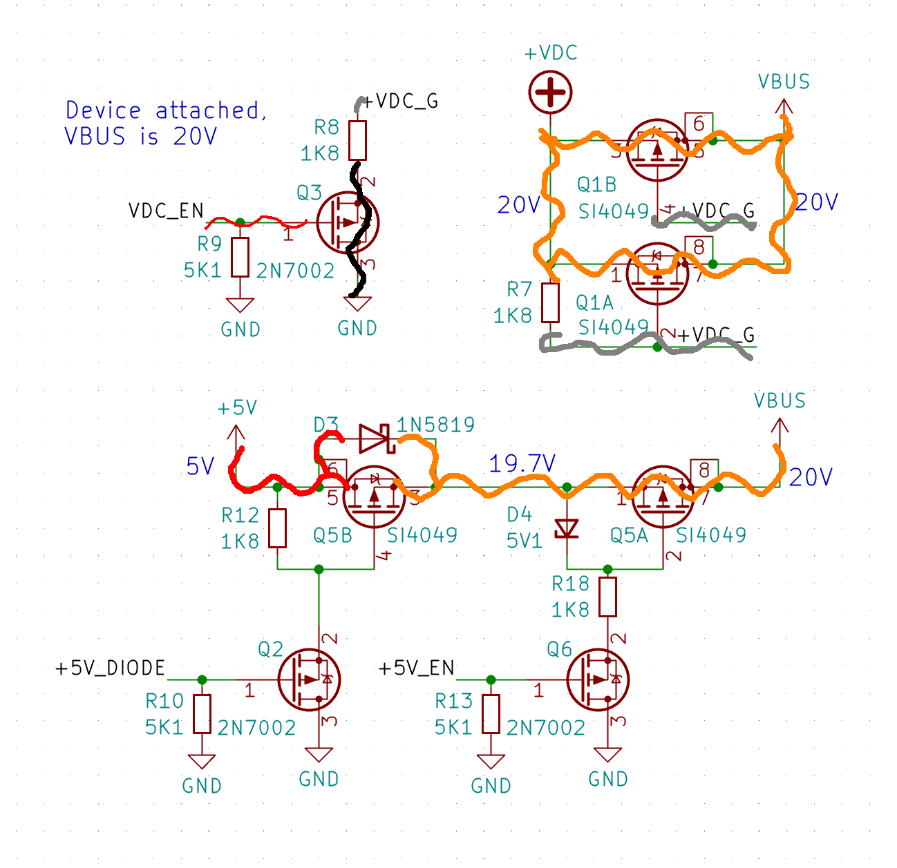
You could use an ideal diode circuit of some sort for backfeeding prevention purpose, but I’ll use a pair of back-to-back FETs driven by NPN transistors, with two separate control GPIOs. For 20 V, I’ll use two FETs connected in parallel – that decreases Rds and heat dissipation; remember, as a rule, FETs in parallel balance each other and spread the current equally between themselves! I’m going to wire up one SI4909DY pair in series for 5 V use, and another with both FETs in parallel for 20 V use.
When I first built this circuit, I put the 20 V FETs back-to-back too, thinking that I’d add a protection mechanism in case one of the FETs got shorted, but they ended up dissipating too much power. So, instead, I’m adding a boot-time VBUS measurement check into the code, that will make the PSU shut down and show an error message in case the 20 V or 5 V FETs get shorted out.
Our PSU needs to support three states – no VBUS on its USB-C output port, 5 V VBUS output, and 20 V VBUS output. Here’s a diagram of how you can achieve these three states with four FETs, isolating VBUS from both the 5 V source and the 20 V source as well as you possibly can. The two FETs switching 5 V are driven individually so that it’s possible to enable 20 V FET while still having diode-separated 5 V on the line up until the very moment 20 V appears on the line. In 5 V mode, both of the FETs conduct and the diode is bypassed. Since we’re relying on the body diode for up to 1.5 A of current flowing through it, I’m adding a Schottky diode in parallel with the body diode, it’s just a good practice for reliability. Having a diode does create a drop in the 5 V voltage, but only in the transition period – it’s bypassed by its FET in 5 V output mode. As for putting the two 20 V FETs in parallel, if there’s no 20 V charger plugged in, 5 V could theoretically leak onto the 20 V rail, but since 5 V is only produced from 20 V, I don’t worry about that.
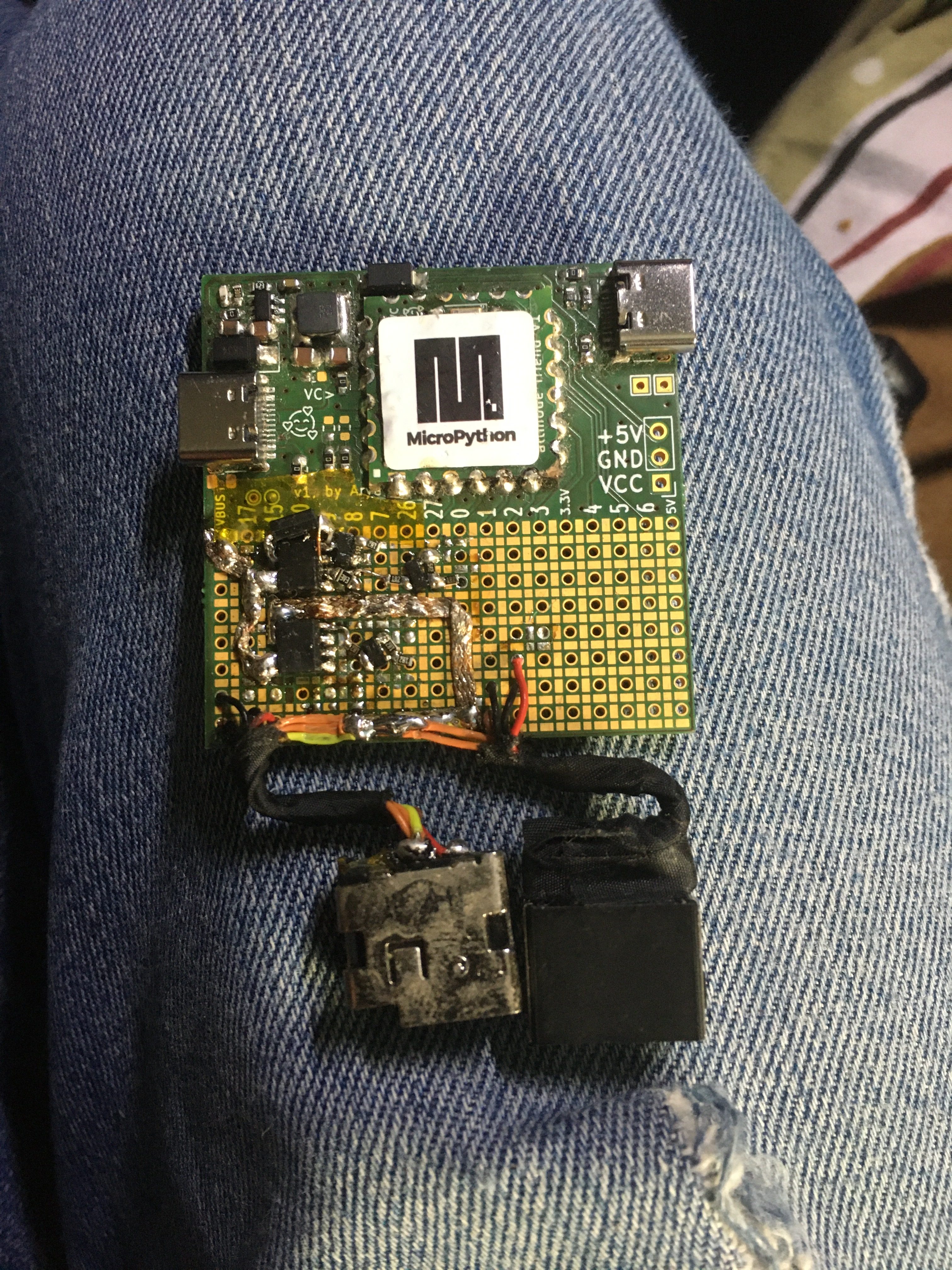
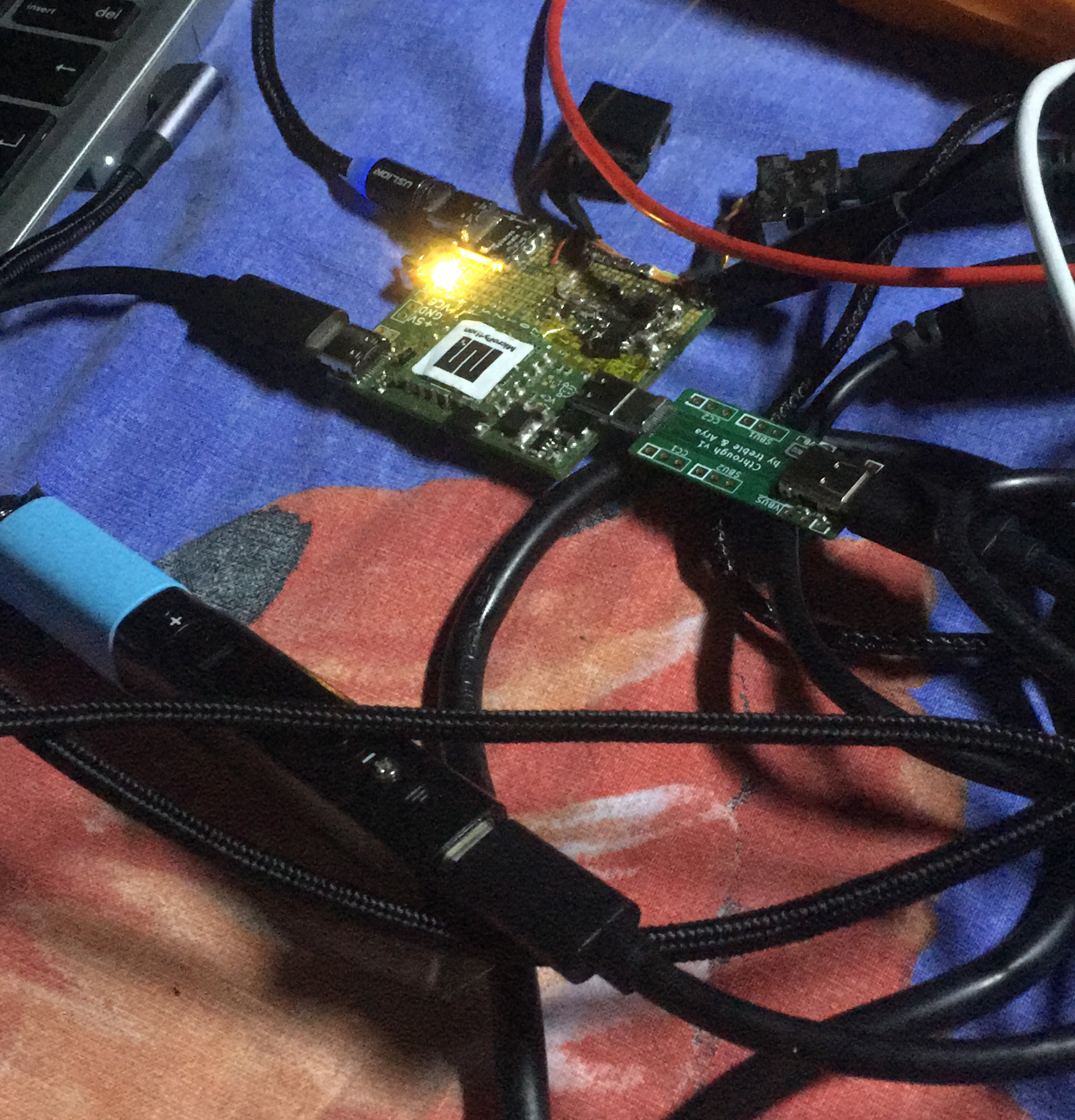
Now, I’ve built this circuit on my PD experiments protoboard, and all that’s left is writing code for it. I’m going to follow the tradition of these articles and write the PD code in MicroPython, running it on a RP2040 with a FUSB302 attached, weaving this code into my small but growing PD stack as I go.
Next article, let’s go through the software, actually test this code on a few USB-C devices – and find out about a surprising and wonderful feature of USB-C that other hackers haven’t yet discovered, but we are about to!