
![usb-and-the-myth-of-500-milliamps-[hackaday]](https://i0.wp.com/upmytech.com/wp-content/uploads/2024/07/193135-usb-and-the-myth-of-500-milliamps-hackaday.jpg?resize=800%2C445&ssl=1)
USB And The Myth Of 500 Milliamps [Hackaday]
If you’re designing a universal port, you will be expected to provide power. This was a lesson learned in the times of LPT and COM ports, where factory-made peripherals and DIY boards alike had to pull peculiar tricks to get a few milliamps, often tapping data lines. Do it wrong, and a port will burn up – in the best case, it’ll be your port, in worst case, ports of a number of your customers.
Having a dedicated power rail on your connector simply solves this problem. We might’ve never gotten DB-11 and DB-27, but we did eventually get USB, with one of its four pins dedicated to a 5 V power rail. I vividly remember seeing my first USB port, on the side of a Thinkpad 390E that my dad bought in 2000s – I was eight years old at the time. It was merely USB 1.0, and yet, while I never got to properly make use of that port, it definitely marked the beginning of my USB adventures.
About six years later, I was sitting at my desk, trying to build a USB docking station for my EEE PC, as I was hoping, with tons of peripherals inside. Shorting out the USB port due to faulty connections or too many devices connected at once was a regular occurrence; thankfully, the laptop persevered as much as I did. Trying to do some research, one thing I kept stumbling upon was the 500 mA limit. That didn’t really help, since none of the devices I used even attempted to indicate their power consumption on the package – you would get a USB hub saying “100 mA” or a mouse saying “500 mA” with nary an elaboration.
Fifteen more years have passed, and I am here, having gone through hundreds of laptop schematics, investigated and learned from design decisions, harvested laptops for both parts and even ICs on their motherboards, designed and built laptop mods, nowadays I’m even designing my own laptop motherboards! If you ever read about the 500 mA limit and thought of it as a constraint for your project, worry not – it’s not as cut and dried as the specification might have you believe.
Who Really Sets The Current Limit?
The specification originally stated – you aren’t supposed to consume more than 500mA from a USB port. At some points, you’re not even supposed to consume more than 100mA! It talked unit loads, current consumption rates, and a good few other restrictions you would want to apply to a power rail. Naturally, that meant enforcement of some kind, and you would see this limit enforced – occasionally.
On the host side, current limiting had to be resettable, of course, and, at the time, that meant either PTC fuses or digital current limiting – both with their flaws, and a notable price increase – per port. Some bothered (mostly, laptops), but many didn’t, either ganging groups of ports together onto a single limited 5 V rail, or just expecting the board’s entire 5 V regulator to take the fall.
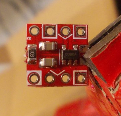
Even today, hackers skimp on current limiting, as much as it can be useful for malfunctioning tech we all so often hack on. Here’s a tip from a budding motherboard designer: buy a good few dozen SY6280’s, they’re 10 cents apiece, and here’s a tiny breakout PCB for them, too. They’re good for up to 2 A, and you get an EN pin for free. Plus, it works for both 3.3 V, 5 V, and anything in between, say, a single LiIon cell’s output. Naturally, other suggestions in comments are appreciated – SY6280 isn’t stocked by Western suppliers much, so you’ll want LCSC or Aliexpress.
Another side of the equation – devices. Remember the USB cup warmer turned hotplate that required 30 paralleled USB ports to cook food? It diligently used these to stay under 500 mA. Mass-manufactured devices, sadly, didn’t.
Portable HDDs wanted just a little more than 2.5 W to spin-up, 3G modem USB sticks wanted an 2 A peak when connecting to a network, phones wanted more than 500 mA to charge, and coffee warmers, well, you don’t want to sell a 2.5 W coffee warmer when your competitor boasts 7.5 W. This led to Y-cables, but it also led to hosts effectively not being compatible with users’ devices, and customer dissatisfaction. And who wants complaints when a fix is simple?
It was also the complexity. Let’s say you’re designing a USB hub with four ports. At its core, there’s a USB hub IC. Do you add current consumption measurement and switching on your outputs to make sure you don’t drain too much from the input? Will your users like having their devices randomly shut down, something that cheaper hubs won’t have a problem with? Will you be limiting yourself to way below what the upstream port can actually offer? Most importantly, do users care enough to buy an overly compliant hub, as opposed to one that costs way less and works just as well save for some edge cases?
Stretching The Limit
500 mA current monitoring might have been the case originally, but there was no real need to keep it in, and whatever safety 500 mA provided, came with bothersome implementation and maintenance. The USB standard didn’t expect the 2.5 W requirement to budge, so they initially had no provisions for increasing, apart from “self-powering” aka having your device grab power from somewhere else other than the USB port. As a result, both devices and manufacturers pushed the upper boundary to something more reasonable, without an agreed-upon mechanism on how to do it.
USB ports, purely mechanically, could very well handle more than 0.5 A all throughout, and soon, having an allowance of 1 A or even 1.5 A became the norm. Manufacturers would have some current limits of their own in mind, but 500 mA was long gone – and forget about the 100 mA figure. Perhaps the only place where you could commonly encounter 500 mA was step-ups inside mobile phones, simply because there’s neither much space on a motherboard nor a lot of power budget to spend.
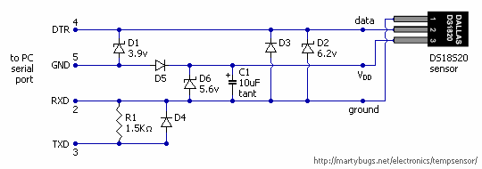
Smartphone manufacturers were in a bind – how do you distinguish a port able to provide 500 mA from a port able to provide 1000 mA, or even 2 A outright? That’s how D+/D- shenanigans on phone chargers came to be – that, and manufacturers’ greed. For Android, you were expected to short data lines with a 200 Ohm resistor, for Apple, you had to put 2.2 V or 2.7 V on the data pins, and if you tried hard enough, you could sometimes use three resistors to do both at once.
Bringing The Standard In Line
The USB standard group tried to catch up with the USB BC (Battery Charging standard), and adopted the Android scheme. Their idea was – if you wanted to do a 1.5 A-capable charger, you would short D+ and D-, and a device could test for a short to check whether it may consume this much. Of course, many devices never checked, but it was a nice mode for smartphones specifically.
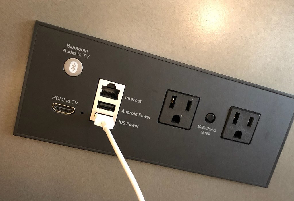
When you’re making a device with a LiIon that aims to consume over an amp and be produced in quantity of hundreds of thousands, safety and charger compatibility is pretty crucial. A less common but nifty charging mode from the BC standard, CDP (Charging Downstream Port), would even allow you to do USB2 and 1.5 A. Support for it was added to some laptops using special ICs or chipset-level detection – you might have had a yellow port on your laptop, dedicated for charging a smartphone and able to put your phone’s port detection logic at ease.
Further on, USB3 took the chance to raise the 500 mA limit to 90 0mA. The idea was simple – if you’re connected over USB2, you may consume 500 mA, but if you’re a USB3 device, you may take 900 mA, an increased power budget that is indeed useful for higher-speed USB3 devices more likely to try and do a lot of computation at once. In practice, I’ve never seen any laptop implement the USB2 vs USB3 current limit checking part, however, as more and more devices adopted USB3, it did certainly raise the bar on what you could be guaranteed to expect from any port.
As we’ve all seen, external standards decided to increase the power limit by increasing voltage instead. By playing with analog levels on D+ and D- pins in a certain way, the Quick Charge (QC) standard lets you get 9 V, 12 V, 15 V or even 20 V out of a port; sadly, without an ability to signal the current limit. These standards have mostly been limited to phones, thankfully.
USB-C-lean Slate
USB-C PD (Power Delivery) has completely, utterly demolished this complexity, as you might notice if you’ve followed my USB-C series. That’s because a device can check the port’s current capability with an ADC connected to each of the two CC pins on the USB-C connector. Three current levels are defined – 3 A, 1.5 A and “Default” (500 mA for USB2 devices and 900 mA for USB3). Your phone likely signals the Default level, your charger signals 3 A, and your laptop either signals 3 A or 1.5 A. Want to get higher voltages? You can do pretty simple digital communications to get that.
Want to consume 3 A from a port? Check the CC lines with an ADC, use something like a WUSB3801, or just do the same “check the PSU label” thing. Want to consume less than 500 mA? Don’t even need to bother checking the CCs, if you’ve got 5 V, it will work. And because 5 V / 3 A is a defined option in the standard, myriad laptops will effortlessly give you 15 W of power from a single port.
On USB-C ports, BC can still be supported for backwards compatibility, but it doesn’t make as much sense to support it anymore. Proprietary smartphone charger standards, raising VBUS on their own, are completely outlawed in USB-C. As device designers have been provided with an easy mechanism to consume a good amount of power, compliance has become significantly more likely than before – not that a few manufacturers aren’t trying to make their proprietary schemes, but they are a minority.