
![under-the-sea:-optical-repeaters-for-submarine-cables-[hackaday]](https://i0.wp.com/upmytech.com/wp-content/uploads/2023/08/136727-under-the-sea-optical-repeaters-for-submarine-cables-hackaday.jpg?resize=800%2C445&ssl=1)
Under the Sea: Optical Repeaters for Submarine Cables [Hackaday]

Once a month or so, I have the privilege of sitting down with Editor-in-Chief Elliot Williams to record the Hackaday Podcast. It’s a lot of fun spending a couple of hours geeking out together, and we invariably go off on ridiculous tangents with no chance of making the final cut, except perhaps as fodder for the intro and outro. It’s a lot of work, especially for Elliot, who has to edit the raw recordings, but it’s also a lot of fun.
Of course, we do the whole thing virtually, and we have a little ritual that we do at the start: the clapping. We take turns clapping our hands into our microphones three times, with the person on the other end of the line doing a clap of his own synchronized with the final clap. That gives Elliot an idea of how much lag there is on the line, which allows him to synchronize the two recordings. With him being in Germany and me in Idaho, the lag is pretty noticeable, at least a second or two.
Every time we perform this ritual, I can’t help but wonder about all the gear that makes it possible, including the fiber optic cables running beneath the Atlantic Ocean. Undersea communications cable stitch the world together, carrying more than 99% of transcontinental internet traffic. They’re full of fascinating engineering, but for my money, the inline optical repeaters that boost the signals along the way are the most interesting bits, even though — or perhaps especially because — they’re hidden away at the bottom of the sea.
Better Than Coax
Most of the long history of transoceanic communications has been dominated by one material: copper. From the earliest telegraph cables right through to the coaxial cables carrying thousands of multiplexed telephone and television signals, copper conductors did the bulk of the work for almost all of the 20th century. That began to change in 1988 with the laying of the first transatlantic fiber-optic telephone cable, TAT-8. With a capacity of 40,000 simultaneous phone calls on just two pairs of single-mode glass fibers (with one pair in reserve), TAT-8 bested the most advanced coaxial transatlantic cables by a factor of ten.
Like coax cables, optical cables require periodic boosting of the signal, especially over TAT-8’s roughly 7,000 km length. Repeaters were spaced every 50 km or so along the cable, housed in long, pressure-rated housings that created bulges in the slim cable, but were still compatible with the cable-laying gear. These repeaters worked by receiving the weakened optical signals with photodiodes, demodulating the signal before running it through semiconductor amplifiers, and converting it back into light using laser diodes. Power for the repeaters was applied to a copper conductor inside the optical cable assembly by equipment in the landing station.
TAT-8 was a fantastic success, to the point where demand exceeded capacity within eighteen months of going into service. It was taken out of service in 2002, in part because in the intervening years, optical cables with vastly more capacity had been laid, rendering TAT-8 obsolete. There was also the matter of the regenerative repeaters; since they needed to demodulate and re-modulate the signals, this limited the changes operators could make to the head-end equipment in the landings. Without the ability to upgrade that equipment, the cable was doomed.
Getting Pumped
But as early as 1985, advances in optical amplifiers were being made that would eventually find their way into submarine cables. That was when a physics grad student named Robert Mears did experiments with erbium-doped glass fibers and showed that they could act as purely optical, low-noise amplifiers in the wavelengths typically used for communications. Within ten years of the first paper on the subject, erbium-doped fiber amplifiers (EDFAs) were slipping into the Atlantic on the TAT-12/13 cable.
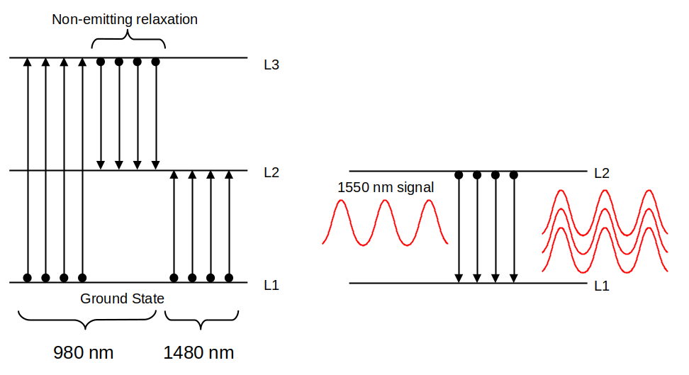
Like many devices we use every day and tend to take for granted, EDFAs leverage the principles of quantum physics and yet are surprisingly simple. EDFAs rely on the fluorescent properties of oxides of the rare-earth element erbium to achieve amplification. When a small amount of erbium (III) oxide is added to the core of a silica fiber, the electrons in the erbium ions can be excited from their ground state (L1) by hitting them with laser light at a specific pumping wavelength. The pumping laser can either be 980 nm, which excites the erbium electrons to the L3 state, or 1,480 nm, which excites them to the L2 state. Practical EDFAs tend to use both 980 and 1,480 nm pumping lasers.
Excitation by the pumping laser leaves the erbium-doped fiber with a population inversion, which is a state where more atoms are in the excited state than the ground state. This creates a medium that’s ripe for disruption, specifically by the passage of a photon at a specific wavelength. For the excited erbium ions, that’s about 1,550 nm, which just so happens to be the wavelength of the infrared lasers used to send signals down an optical cable. When 1,550 nm photons hit the excited erbium ions, it induces them to return to their ground state, releasing a photon of the same wavelength in the process. Each relaxation releases a photon, each of which has the same wavelength and same phase as the incident photon and is traveling in the same direction, which results in massive amplification of the incoming 1,550 nm signal.
In theory, EDFAs are extremely simple — just a loop of doped fiber 10 to 20 meters in length, a laser diode for pumping, and the necessary optical components to join the amplifying loop to the incoming and outgoing fiber and multiplex the two together. The only electronics needed are those that drive the pumping diode, plus whatever circuits are needed for monitoring the health of the amplifier and controlling it remotely.
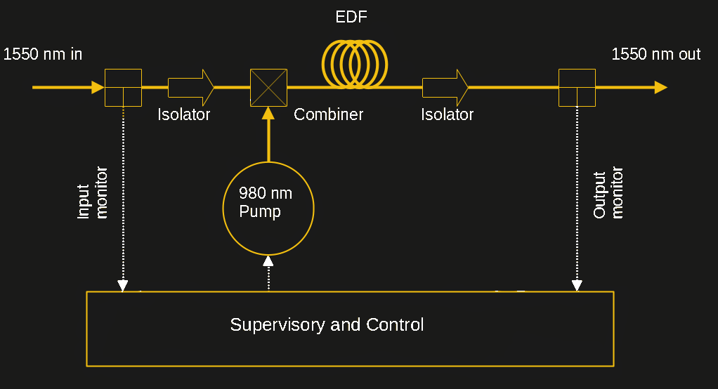
Real-world EDFAs are a bit more complex, tending to have a host of other optical components, like isolators on the input and output fibers that prevent unwanted reflections from leaking back from the output side. Even with these elaborations, though, EDFAs are simple enough to be manufactured as compact modules which can be installed in rack-mount enclosures — at least for amplifiers for land-based fiber optic cables.
Taking a Dip
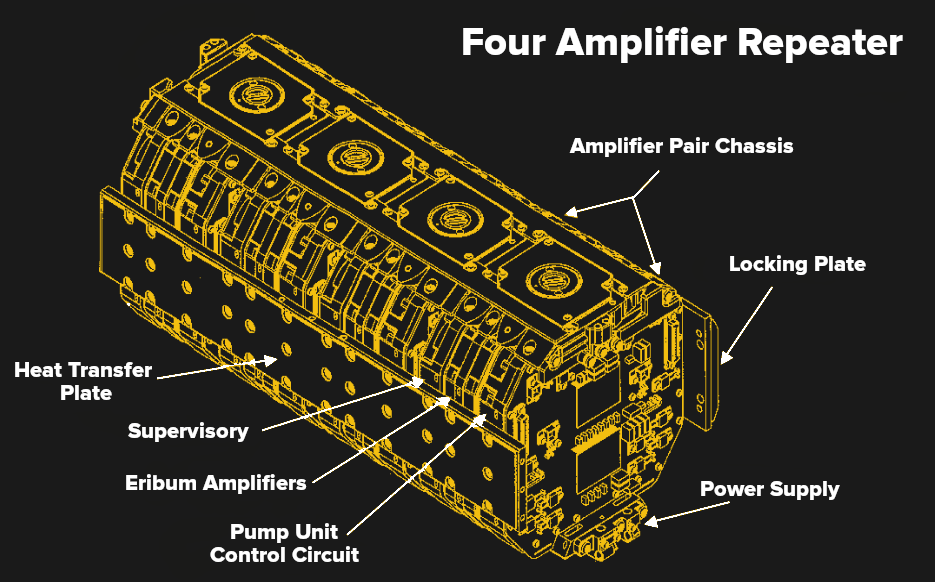
Things change appreciably for the “wet plant” equipment of submarine cables, which as the name suggests is everything that runs under the ocean. Not only must each repeater squeeze multiple EDFAs — one for each fiber in the cable — into a package compact enough to be handled by the cable-laying gear, but it also has to be able to withstand the rigors of operating in one of the most hostile environments on the planet. And then there’s the matter of providing power to the pumping lasers and supervisory electronics over massive distances, itself a non-trivial task. Add in a design life of 25 years — while it’s not impossible to recover and repair a faulty repeater, it is neither cheap nor convenient — and a lot of engineering goes into these devices.
Depending on the needs of the cable owner and the route over which the cable will be laid, repeaters can potentially lie up to 8,000 meters below the surface. The pressure at that depth is about 78 MPa, or over 11,000 psi, which has to be resisted by the repeater housing itself and every joint and seal between the housing and the cable itself. Housings are generally made of either titanium or a beryllium copper alloy such as C17200, which is almost as strong and as hard as steel, but exhibits excellent resistance to the corrosive effects of seawater. It also has excellent electrical and thermal conductivity, with the latter being extremely important when it comes to dissipating the excess heat generated by the pumping lasers.
Submarine repeaters get their power over a dedicated copper sheath wrapped around the glass fibers at the center of the cable, with a return path through the seawater surrounding the cable. Power distribution equipment at the cable landing injects high DC voltage onto this conductor, with every repeater connected in series. Power is considerable, typically in the 10- to 15-kilovolt range and between 1 and 2 amps. Voltage drop at each repeater depends on the number of fiber pairs it services, but is typically between 30 and 70 volts.
With submarine repeaters, redundancy is the name of the game. Individual components are, of course, selected for high reliability. But eventually something will fail, so it’s critical to have a backup instantly available. This is most apparent with the arrangement of pumping diodes, which are obviously the most likely component to wear out. Early submarine EDFAs used a “2×2” redundancy scheme, where each amplifier module servicing a transmit and a receive fiber pair had two pump lasers that shared a common driver circuit. This provided at least some backup; in the event that one pump laser failed, cable operators could switch over to the backup pump. A better scheme is “4×2” redundancy, where each pair of amplifiers shares four pump lasers linked together by an optical coupler. Since a single pump can run both the transmit and receive fibers, an amplifier can still run if three of the pumps fail. Better still is “pump farming,” in which up to 16 pumps are available to route to as many as 16 fiber pairs through a complex optical fiber switching network. Pump farming provides a huge amount of redundancy as well as the flexibility to reconfigure the cable on the fly.
Not For Everyone
For as ubiquitous as EDFA amplifiers have become on long-haul subsea routes, they don’t make an appearance on every cable. Some cable routes are short enough that the line can be completely repeaterless, with obvious benefits to owner and operator alike in terms of initial and ongoing costs. Other regional routes that are a bit too long for a truly repeater-free design can take advantage of ROPA, or remote optically pumped amplifiers. These are essentially the same as EDFAs with the exception of the pumping lasers being installed as part of the “dry plant” equipment at the cable landings, and transmitted to the ROPA repeaters along a dedicated optical fiber. This eliminates the need for a power conductor in the cable as well as eliminating the power distribution gear, and makes the repeaters simpler and more compact.
Another advancement in subsea optical amplifiers is the Raman amplifier, which uses stimulated Raman scattering to amplify the signal. Incoming signal photons at one frequency collide with pump photons at a slightly higher frequency in a non-linear optical medium, which can be either a separate loop of optical fiber or the signal-carrying fiber itself. The inelastic collision transfers some of the energy from the pump photons to the signal photons, resulting in amplification. Raman amplifiers require higher power for the pump lasers — about 500 mW or more of optical power — but the advantage is that the amplification can be distributed along the length of the transmission fiber, resulting in the need for fewer repeaters. Raman amplifiers for submarine applications are relatively new, and not applicable for all cables — they generally can’t be used on transpacific cables due to the higher electrical power requirements — but they are making inroads into transatlantic and regional cables.