
![secrets-of-the-old-digital-design-titans-[hackaday]](https://i0.wp.com/upmytech.com/wp-content/uploads/2024/07/196349-secrets-of-the-old-digital-design-titans-hackaday.png?resize=546%2C274&ssl=1)
Secrets of the Old Digital Design Titans [Hackaday]
Designing combinatorial digital circuits seems like it should be easy. After all, you can do everything you want with just AND, OR, and NOT gates. Bonus points if you have an XOR gate, but you can build everything you need for combinatorial logic with just those three components. If all you want to do is design something to turn on the light when the ignition is on AND door 1 is open OR door 2 is open, you won’t have any problems. However, for more complex scenarios, how we do things has changed several times.
In the old days, you’d just design the tubes or transistor circuits you needed to develop your logic. If you were wiring up everything by hand anyway, you might as well. But then came modules like printed circuit boards. There was a certain economy to having cards that had, say, two NOR gates on a card. Then, you needed to convert all your logic to use NOR gates (or NAND gates, if that’s what you had).
Small-scale ICs changed that. It was easy to put a mix of gates on a card, although there was still some slight advantage to having cards full of the same kind of gate. Then came logic devices, which would eventually become FPGAs. They tend to have many of one kind of “cell” with plenty of logic gates on board, but not necessarily the ones you need. However, by that time, you could just tell a computer program what you wanted, and it would do the heavy lifting. That was a luxury early designers didn’t have.
Basis
How can you do everything with a NOR gate? Easy if you don’t mind spending gates. Obviously, if I need a NOR gate, I’m done. If I need an OR gate, I just feed the output of a NOR gate to all the pins of another NOR gate. The output of the second gate will be the OR of the first gate’s inputs.
DeMorgan’s theorem tells us that if NOT(A OR B) is the same as (NOT A) AND (NOT B). It is!
| A | B | NOT A | NOT B | NOT(A OR B) | (NOT A) AND (NOT B) |
| 0 | 0 | 1 | 1 | 1 | 1 |
| 0 | 1 | 1 | 0 | 0 | 0 |
| 1 | 0 | 0 | 1 | 0 | 0 |
| 1 | 1 | 0 | 0 | 0 | 0 |
So you can create a NOT gate with a NOR gate (or a NAND gate) and an AND/NAND gate by mixing up NOR and NOT gates. Conversely, you can create OR/NOR gates by mixing up NAND and NOT gates. So, either way, you are covered.
The only problem is figuring out how to express any arbitrary expression as a bunch of NOR or NAND gates. A common way to do this is to have a “product of sums” or “sum of products” arrangement. In this context, a product is an AND gate, and a sum is an OR gate. This also works with things where you use diodes and wired AND logic, such as those you find in a programmable logic array or open collector arrangements. Think about it. A bunch of open collector outputs tied to a pull up resistor acts like a giant AND gate. Any low input causes a low output.
Suppose you wanted to determine whether a two-bit binary number is odd or even. Yes, yes, there is an easy way to do that, but assume you don’t know that yet. Let’s assume the most significant bit is A and the least significant is B. Further, we’ll use the notation A’ for NOT(A). AB is A AND B, while A+B is A OR B. The two odd values are 01 and 11, so we can set up another logical Y that is true when we have one of those OR the other:
Y=A'B + AB
Troubleshooting
This works, of course. But if you are adept at troubleshooting digital logic, you might notice something — again, assuming that you don’t already know the answer to this problem. The output, Y, doesn’t really depend on A at all because we have A’B or AB together. So just intuitively, we know the real answer is Y=B. No gates are needed at all!
But how would we figure out a minimum in a more complex example? For instance, suppose you have a four-digit number and want to drive a seven-segment LED. Segment a, for example, is the top bar of the figure 8 that forms the display. It should be on for inputs 0, 2, 3, 5, 6, 7, 8, and 9. Then, you need to do this for six other segments. Hard to see exactly how to decode that, right?
Methods
Before computers would do it for you, there were two common methods to resolve things like this without resorting to brute force. The most notable of these is the Karnaugh or K map. These are great for a small number of inputs. Let’s go back to the two-bit number. Our K map looks like this one.
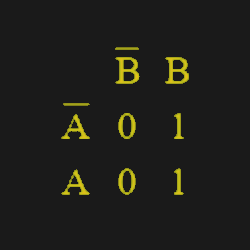
Each of these four cells containing a zero or one represents a single AND gate with A and B set as shown (that is, if A or B are true or false). The number in the cell is the output in that state. If you don’t care about an output given a certain state of inputs, you can put an X in that square and treat them the same as a 1 if you want to (but you don’t have to). By the way, these maps were made using the very useful K map solver you can find online.
Next, you circle all the 1’s that are next to each other in a rectangle including any that wrap around the edges. When you have a bunch of ones clustered together, you can wipe out the variables that change from 0 to 1 in the group.
In this case, the 1’s cover both A and A’, so we can easily see the answer is Y=B. Of course, we knew that already, but you can figure it out easily using a map like this, even if you don’t already know the answer.
For a map this small, you don’t have many options, but the number of 1s (or Xs) in an implicant — a group — must be a power of two. So you can draw a rectangle around two cells or four, but not three.
Bigger, My My…
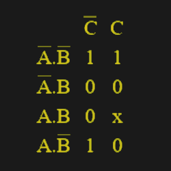
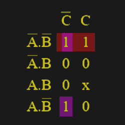
Note that the values of A and B only change by one bit in adjacent cells. So, a 3-variable K map looks like this is the one adjacent. Note that the left-hand column reading from top to bottom goes 00, 01, 11, 10. So, only one bit changes at a time (like a grey code).
In this case, the prime implicants — the parts that matter — are A’B’ and B’C’. That’s because the top row strikes the C input when AB=00 and the top left 1 and the bottom left 1 join to cancel out A.
Every rectangular grouping that covers a power of two cells is a prime implicant. Sometimes, a group will cover terms that other groups will also cover. In that case, that group is not an essential prime implicant but, rather, a redundant prime implicant. But if even one square only belongs to a group, then that group is an essential prime implicant and will have a role in the final result. Sometimes, you’ll have several prime implicants that cover each other so that you can pick one or the other, and it doesn’t matter which one. Those are known as selective prime implicants.
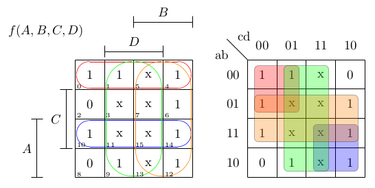
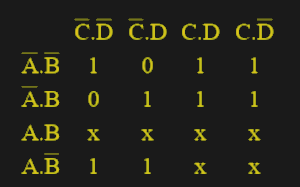
As you can see below, once you have four bits, the K map gets large. Beyond 4 bits, it is usually impractical without switching how you draw the map. Remember the 7-segment decoder example? Here is the K map for segment A of a decoder that accepts numbers from 0 to 9. Note the Xs for numbers larger than 9. If you draw circles around the groupings of 1s, you can develop the formula: Y=C+A +B’D’+BD. That’s much easier than trying to do it without a K map. The C is due to the right-hand columns (remember to include the Xs when it helps you). The A term is due to the bottom two rows. The other two terms pick up the stray 1’s not covered by those two groups. Of course, to design an entire decoder, you’d need six more K maps, one for each segment.
It is also possible to group the 0s instead of the 1s and obtain a product of sums. The process is similar but you use the 0’s and not the 1’s.
The real challenge is when you want to go beyond four bits. For that, you often go to a table-like format known as the Quine McCluskey method. Or just use a computer. We won’t judge.
Of course, if you want to make complex digital designs, you need a clock. But you can still use maps where you need combinatorial logic in a synchronous design. We mentioned you can make anything out of AND, OR, and NOT. But you can get those gates using a multiplexer or even a relay, which is, after all, just a mechanical multiplexer. Come to think of it, you can make logic gates out of darn near anything.
Banner image by [Kit Ostrihon], demonstrating multidimensional K-maps
Thumbnail image: “K-map 6,8,9,10,11,12,13,14 anti-race” by [Cburnett]