Precise Positioning with the RP2040 [Hackaday]

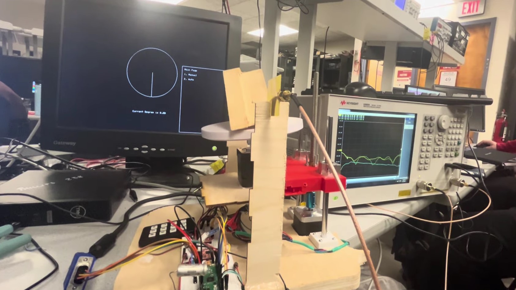
Microwave imaging is similar to CT imaging, but instead of X-rays, the microwaves are used to probe the structure and composition of an object. To facilitate experimentation with microwave imaging, [Zehao Li] and [Kapil Gangwar] developed a system based on the RP2040 to control the height and rotation of a test object.
Their control system has a refreshingly physical user interface—a keypad. The keypad is used to configure the object’s position and the scanning step size, while user menus and the sample position are displayed in a clean and uncluttered interface over VGA. The RP2040 runs a multi-threaded program to handle user input, VGA display, and precise driving of two stepper motors for sample positioning.
The microwave imaging was performed by measuring the RF transmission over 2.5-8 GHz between two Vivaldi antennas on either side of the sample at a variety of angles. 2D cross-sections of the test object were reconstructed in Matlab using filtered back-projection. In this proof-of-concept demonstration, a commercial vector network analyzer was used to collect the data, but one could imagine migrating to a software defined radio (SDR) in the future.
A video demonstrating the system is embedded below the break. If you’re interested in DIY radio imaging, you might be interested in this guide to building your own synthetic aperture radar setup, or this analysis of an automotive radar chip.

![precise-positioning-with-the-rp2040-[hackaday]](https://i0.wp.com/upmytech.com/wp-content/uploads/2024/01/160382-precise-positioning-with-the-rp2040-hackaday.jpg?resize=800%2C445&ssl=1)