
![portable-router-build:-finding-an-lte-modem-[hackaday]](https://i0.wp.com/upmytech.com/wp-content/uploads/2024/08/205770-portable-router-build-finding-an-lte-modem-hackaday.jpg?resize=800%2C445&ssl=1)
Portable Router Build: Finding An LTE Modem [Hackaday]
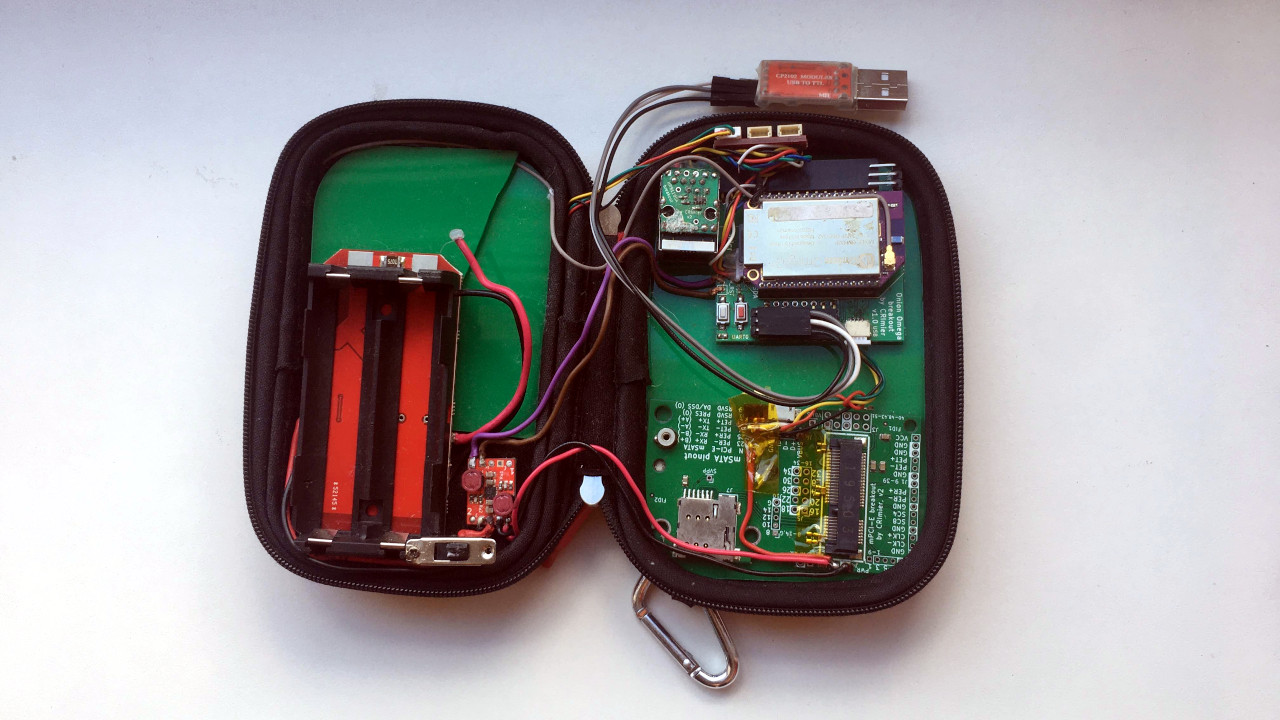
Ever want your project equipped with a cellular interface for a data uplink? Hop in, I have been hacking on this for a fair bit! As you might remember, I’m building a router, I told you about how I picked its CPU board, and learned some lessons from me daily-driving it as a for a bit – that prototype has let me learn about the kind of extra hardware this router needs.
Here, let’s talk about LTE modems for high data throughput, finding antennas to make it all work, and give you a few tips that should generally help out. I’d like to outline a path that increases your chances of finding a modem working for you wonderfully – the devices that we build, should be reliable.
Narrowing It Down
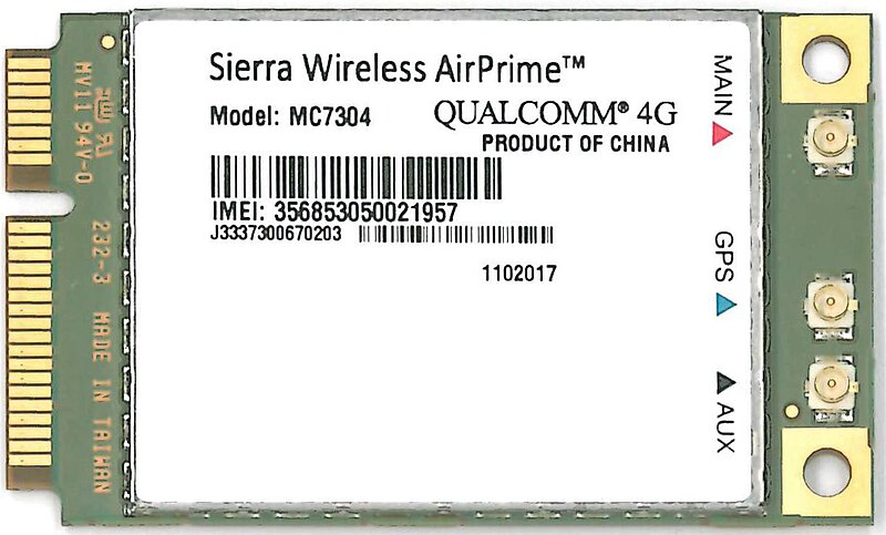
If you look at the LTE modem selection, you might be a little overwhelmed: Simcom, Qualcomm, uBlox, Sierra, Telit, and a good few other manufacturers package baseband chipsets into modules and adjust the chipset-maker-provided firmware. The modems will be available in many different packages, too, many of them solderable, and usually, they will be available on mPCIe cards too. If you want to get a modem for data connections for a project, I argue that you should go for mPCIe cards first, and here’s why.
A mPCIe or M.2 card is a standardized package with everything you need – just connect 3.3 V at about 1-2 A, your data link, and a SIM slot. It frees you up from wiring up everything needed for the bare module to work, soldering the modules that often come in LGA packages, routing antenna connector tracks with proper impedance and adding antenna matching networks, and – all you need is a mPCIe socket and some capacitors next to it.
Using a module makes sense if you’re making something really tiny – and even then, you should test with a mPCIe card in the first revision, which is why modem manufacturers usually have them available in the first place: mPCIe cards are testing platforms. A lot of mPCIe modules are also available cheaply, since they’re also used in laptops, so the second-hand market in your country is going to have some mPCIe cards you can try out, and so will eBay.
Then, there’s the interface question. You might have looked into embedded modem datasheets already. Often, you will see a UART interface, maybe SPI or even SDIO, and, invariably, USB. If you are doing low-throughput data, UART or anything else might just do wonderfully. For “building an LTE uplink router” purpose, the easiest interface to use is USB, and the reason is multi-fold. It’s the most popular path, so you will find more modem options, more documentation, more open-source support, and encounter fewer problems along the way.
USB has been the most convenient way to get an LTE uplink for a while now – and it’s what the industry has chosen. It’s a high throughput link, it’s standardized, and it has even been converging on open-source-friendly and well-travelled interfaces. If a particular USB modem doesn’t work out of the box, you are significantly more likely to find someone else having faced and solved the same problem, just because plugging a USB device into your port is easy.
If you’re using a M.2 modem, you might even find a USB3 option, in case you want your uplink to be seriously high-speed! In this prototype, I’m using a mPCIe breakout, and for testing out M.2 router cards, I am using a mPCIe to M.2 adapter.
All done? Nope. You do need testing, however, because you can’t just pick any modem. You might have to try one, two, or three different modems before you settle on a workable option, and the reason is simple.
Some Tailoring Required
Specifically, configuration interfaces are where things start to break. Older software modems use a virtual serial port over USB for both data and configuration. In slightly more recent times, you would get a combination of a virtual Ethernet card for data and a serial port for AT command configuration.
AT commands have gotten old, however, so interfaces like QMI have taken hold, and now you better use it, even though AT commands are the traditional way. QMI configuration is often needed for the new and relatively less explored interfaces. Sometimes a feature is broken when configured through UART, but works over QMI. Sometimes the UART connection bringup process is just not as well documented. It makes sense – at some point, we need to shed the cruft of the Hayes command set, so don’t get too comfortable. Firmware loading tools are another gotcha. With some old modems, like the Gobi cards, you need a loader script and a matching firmware to go with it. Be prepared to try out a firmware image or two before the modem works the way you need it to. And be prepared to hit dead ends.
This means that you will want to have a setup where you can try out a few different modems if needed. Thankfully, you have a mPCIe socket like I suggested, right? Again, it’s just USB and an amp at 3.3 V; you don’t even need any GPIOs to spare. Some modems even support direct power from a single-cell LiIon battery. This is explicitly stated in the M.2 standard, so if you opt for a M.2 B-key slot, you might be able to skip on a voltage conversion step.
Getting Antennas Quickly
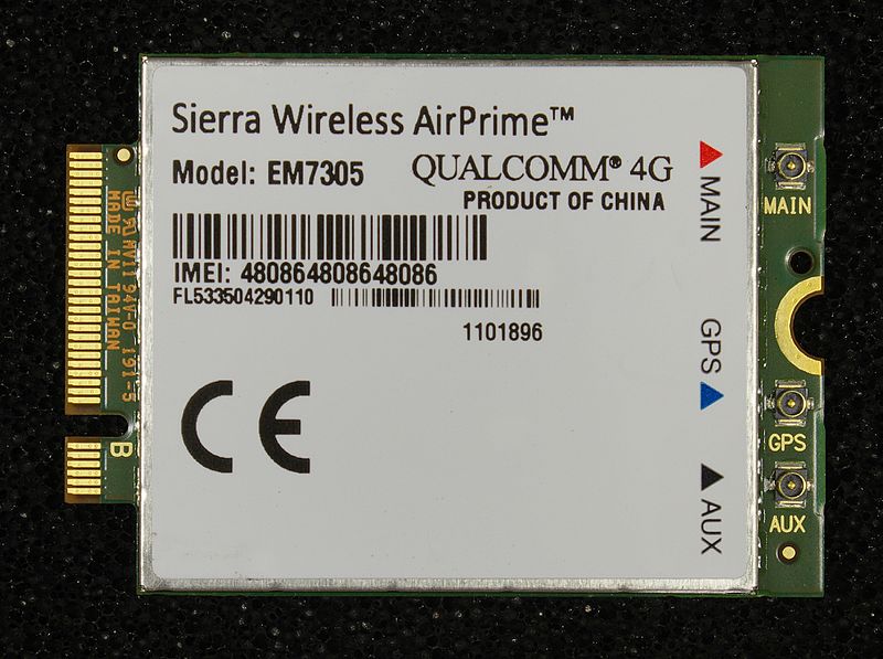
Switching between M.2 and mPCIe can be done with a simple adapter. But beware – they will also use different antenna connectors, with mPCIe modems using uFL connectors and M.2 modems using wFL. So let’s talk about antennas.
You shouldn’t connect a modem to a network without an antenna attached. Chances are, your modem has antenna detection circuitry built-in, but there’s always the rare modem that will try to transmit out of an empty antenna socket and gets its signal reflected back into itself, possibly damaging its transmitter circuits. So, you have a mPCIe modem and it needs antennas that can work at LTE frequencies – how to proceed?
The simplest answer is to get some laptop WWAN antennas out of old laptops, or buy a set of replacement laptop WWAN antennas. These are the easiest two ways to find an antenna with a uFL connector that works for LTE. Don’t use WiFi antennas – they’re tuned for 2.4 GHz in a way that will likely make them useless for WWAN. The antennas that I currently use have been taken out of a Thinkpad that didn’t even have a WWAN card inside. These antennas tend to be designed to work from within the laptop chassis, sure, but they should be good enough outside of it. One nuance – they will have long cables, so you will want to shorten them to your liking or tuck them away somewhere.
Don’t have laptop antennas? Aliexpress will deliver, but you have to be careful there, as not all antennas sold as “LTE” are actually capable of working at these frequencies, mis-labelling and shoddy tuning is commonplace when it comes to hobbyists, because we often don’t really check. If you don’t have something like a NanoVNA, you will want to at least do some simple tests – buy a few antennas, swap them in one by one, remembering to power the modem down, and check the RSSI and the data rates. Otherwise, you can get antennas from specialty shops, but be prepared to pay a bit extra and maybe need some uFL to SMA adapters.
As long as you get the proper antennas and distinguish between wFL and uFL connectors when getting them, you should be in the clear, and that’s about all you need to have an LTE modem module used in your project.
Debug Interface For a Rainy Day
Here’s the last part to mind – you will want to make your initial prototypes flexible for debugging, especially for OpenWRT, which doesn’t have much of an onboard debugging toolkit. For instance, if you have a USB connection in your system, make it tappable so that you can plug a USB cable and have the modem be rerouted to an external device. A single USB2 2:1 mux and a USB-C connector should do wonders – two pairs of zero ohm jumpers are tempting but note that they increase the iteration time a lot when debugging.
Modems are tested on particular OSes, mostly Windows in practice, so when you’re facing a problem, you really want to be able to figure out if this a problem in your drivers, in your power supply, or in your modem’s firmware. How will you update your modem’s firmware for testing purposes, will you have to port a firmware update tool to OpenWRT, or will it be as simple as plugging a cable into a different computer? If your link is dropping out, can you easily check whether that happens if you use a full-fledged Linux computer with an Ubuntu install, or a Windows VM? These are good reasons to have a separate USB line.
So to sum up: use a socket like M.2 or mPCIe so that you can test modem compatibility and stability. Modems are black boxes with closed firmware, and you have to make sure you don’t lock yourself into a glitchy one by having designed a board for a bespoke footprint LGA or QFN-like module. When getting antennas, laptop antennas are an easy shortcut; otherwise, get a few different antennas and do some range tests. And finally, make your USB connection tappable because it helps for debugging.
The modem I went is the EC25 mPCIe card – it’s a card that was put into a lot of laptops, and it even has a GPS antenna hookup point, which is nice to have. Funnily enough, it appears to be at least somewhat compatible with the open firmware that the PinePhone EG25 modem has – we might talk about that in imminent future. Next time, I’d like to talk about OpenWRT and all the ways you can hack on it – it’s a wonderful Linux distribution, but it’s different from the others, and I hope that showing my workflow can help you!