
![linear-feedback-shift-registers-for-fpgas-[hackaday]](https://i0.wp.com/upmytech.com/wp-content/uploads/2024/04/177372-linear-feedback-shift-registers-for-fpgas-hackaday.png?resize=800%2C250&ssl=1)
Linear Feedback Shift Registers for FPGAs [Hackaday]
If you want to start an argument at a Hackaday meeting, you have only to ask something like “How much does this weigh?” or “What time is it?” But if you really want to start a street brawl, you can always say, “Are these numbers random?” Making random numbers that are actually random is actually a tough nut to crack. Most of what we do is, technically, pseudo-random (but we’ll say random number and assume you know what we mean). One way to generate seemingly random sequences is to use a linear feedback shift register or LFSR. You can use LFSRs in software, but they are also very useful in hardware design and [Adam Taylor] takes us through his use of them on FPGAs in a recent post.
As [Adam] points out, they not only generate random-like patterns but they are often used as high-performance counters and in error detection and correction schemes. As the name implies, the mechanism is a simple shift register with one or more of its outputs fed back around to the input. How can that be random? Well, it can’t be, but it is often good enough for places where you need a sequence of numbers. Depending on how you organize the outputs — or taps — and how you feed them back means you can control the pseudo-random sequence.
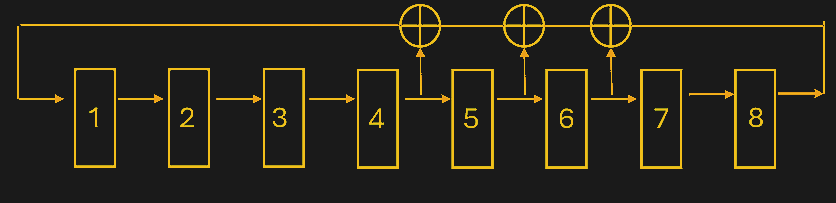
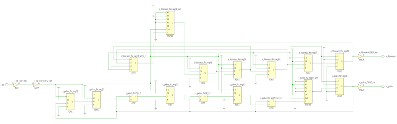
There are two common methods for creating LFSRs. A Fibonacci-style design uses XOR (or inverted XOR) gates in the feedback loop. For example, consider an eight-stage counter. The post shows the output of flip flop 4, feeding an XOR gate that drives the counter’s input. The other input of the XOR gate is the output of another XOR gate that receives input from flip flop 5 and the output of yet another XOR gate. That XOR gate receives its inputs from flip flop 6 and the output of the shift register.
The Galois scheme is similar, but uses the XOR gates in the shift path. In other words, the output of the shift register directly feeds the input, but it also feeds several XOR gates that go between the flip flops. Why choose one over the other? Read the post. The summary is that it depends on how your FPGA resets and what kind of support it has for shift registers so, as usual, it pays to understand what’s going on in the FPGA fabric.
As for where to put the taps, it depends on how you want the pattern to repeat. If you want the repeating kept to a minimum, you can look them up in a table based on research from [Wayne Stahnke] and popularized by Xilinx in an app note. [Solomon Golumb] also published tables of taps for maximum sequence generation. As you might expect, there’s a program that will help you if you don’t want to use the tables.
The math may be hairy, but implementing this in hardware is simple if you ever need a random-looking sequence. Maybe you want a random flicker in your fake candle. You can do it with relays, even.