![friendly-flexible-circuits:-the-cables-[hackaday]](https://i0.wp.com/upmytech.com/wp-content/uploads/2024/02/166932-friendly-flexible-circuits-the-cables-hackaday-scaled.jpg?resize=800%2C445&ssl=1)
Friendly Flexible Circuits: The Cables [Hackaday]
Flexible cables and flex PCBs are wonderful. You could choose to carefully make a cable bundle out of ten wires and try to squish them to have a thin footprint – or you could put an FFC connector onto your board and save yourself a world of trouble. If you want to have a lot of components within a cramped non-flat area, you could carefully design a multitude of stuff FR4 boards and connect them together – or you could make an FPC.
Flexible cables in particular can be pretty wonderful for all sorts of moving parts. They transfer power and data to the scanner head in your flat-bed scanner, for instance. But they’re in fixed parts too. If you have a laptop or a widescreen TV, chances are, there’s an flexible cable connecting the motherboard with one or multiple daughterboards – or even a custom-made flexible PCB. Remember all the cool keypad and phones we used to have, the ones that would have the keyboard fold out or slide out, or even folding Nokia phones that had two screens and did cool things with those? All thanks to flexible circuits! Let’s learn a little more about what we’re working with here.
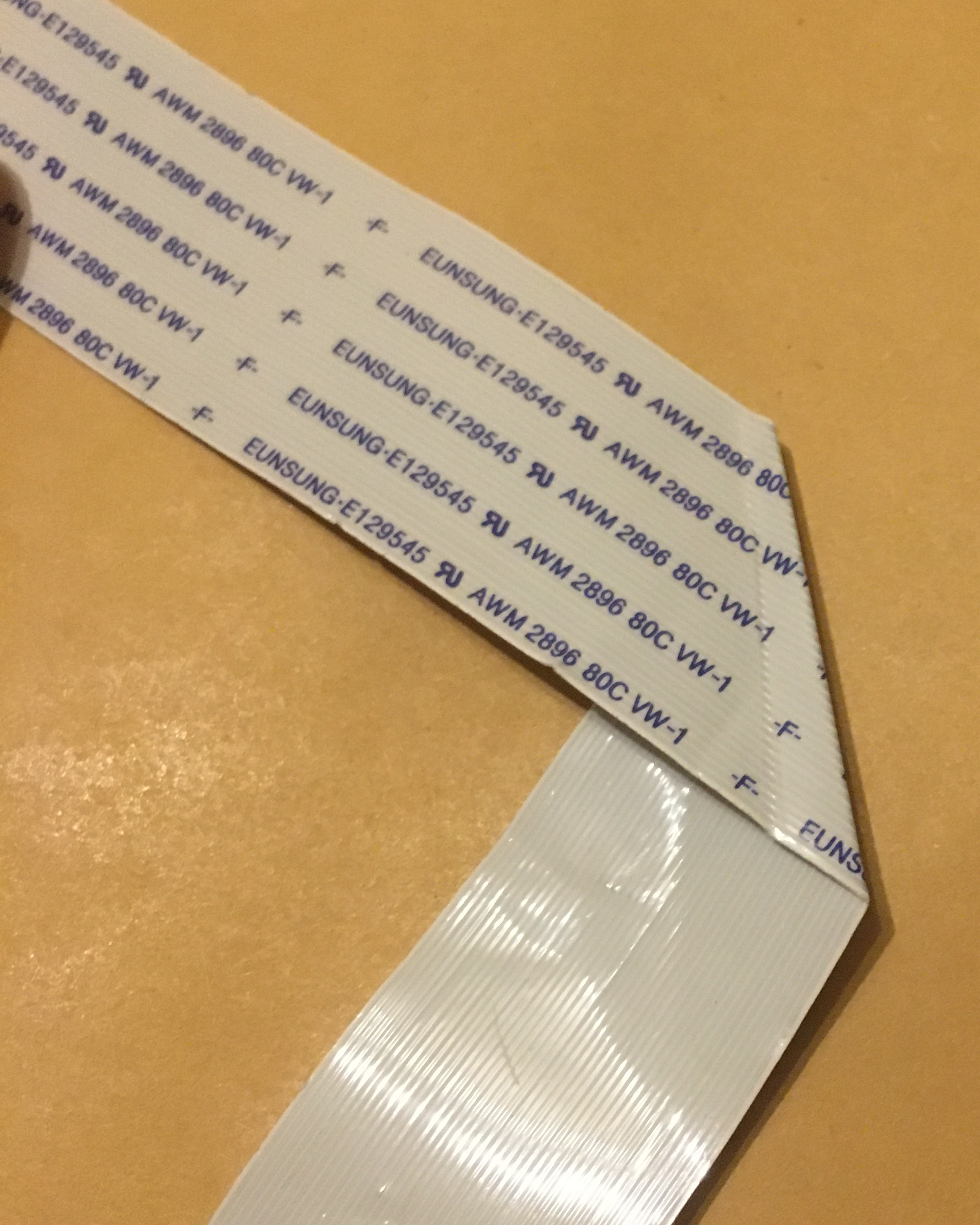
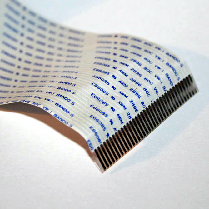
FFC and FPC, how are these two different? FFC (Flexible Flat Cable) is a pre-made cable. You’ve typically seen them as white plastic cables with blue pieces on both ends, they’re found in a large number of devices that you could disassemble, and many things use them, like the Raspberry Pi Camera. They are pretty simple to produce – all in all, they’re just flat straight conductors packaged nicely into a very thin cable, and that’s why you can buy them pre-made in tons of different pin pitches and sizes. If you need one board to interface with another board, putting an FFC connector on your board is a pretty good idea.
An FPC (Flexible Printed Circuit) is a custom flexible PCB, usually of dark orange colour, same colour as kapton tape. These are fundamentally always a custom design – you can pay to have someone produce your FPC design, just like you would have any PCB produced. You could say that an FPC is really just a PCB that’s very thin and bendy – which makes them wonderful for all sorts of purposes! You can make FPCs for building wearables, medical technology, PCB patches, and you can produce FPCs that act as FFC interconnects if you want better signal integrity, too!
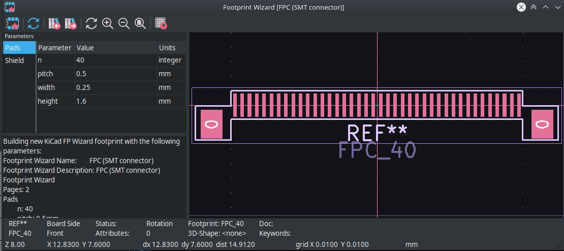
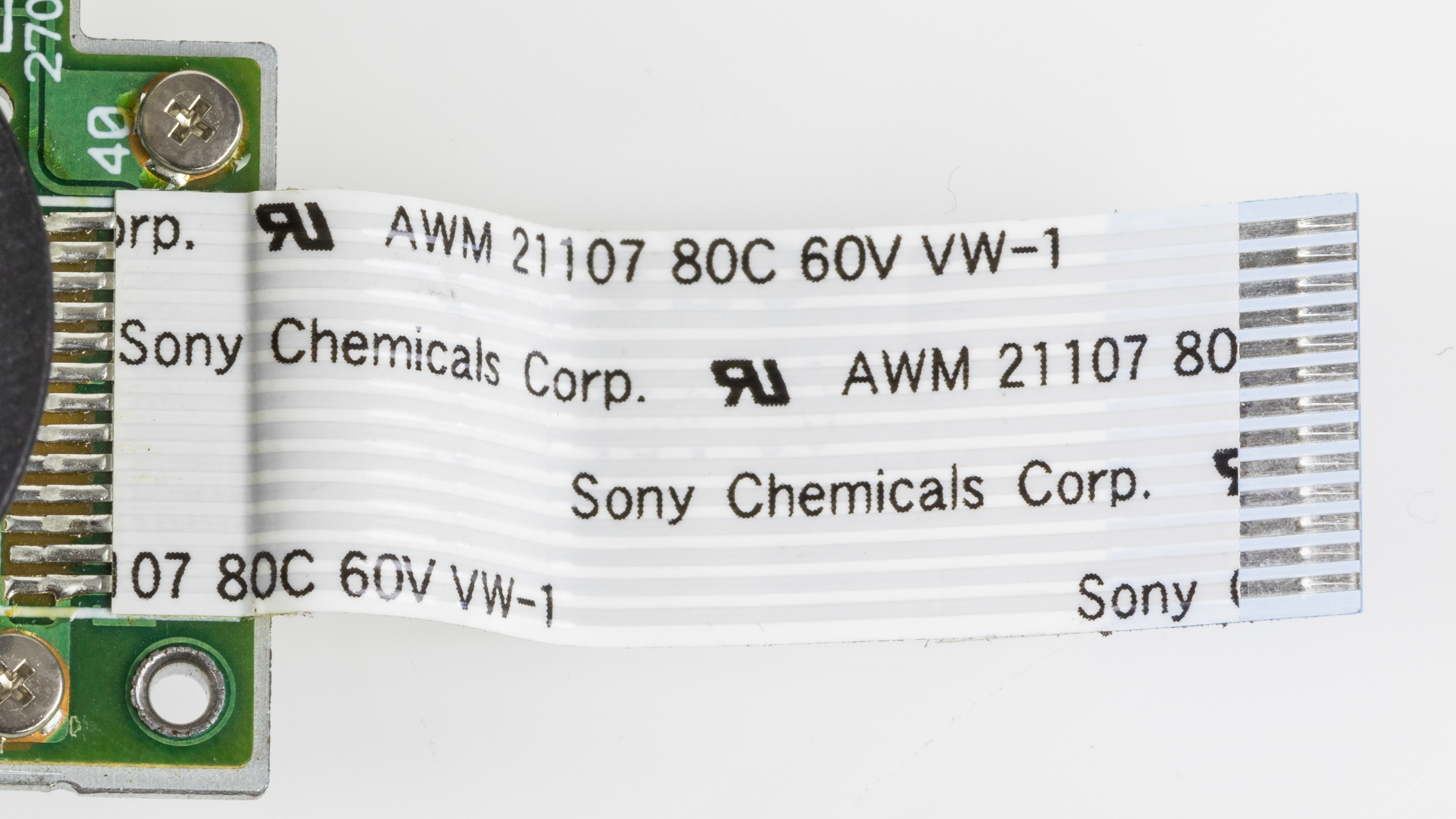
There’s four common pin pitches for FFCs – 1 mm, 0.8 mm, 0.5 mm and 0.35 mm. 1.27 mm FFCs exist but are pretty rare. The larger FFCs have straight contacts as you’ve commonly seen them, and 0.35 mm pitch FFCs have the exposed pins staggered at the connector ends. In fact, 0.35 mm FFCs are most likely to be flex PCBs built for FFC purpose, dark orange instead of white, because the contact staggering seems to require an FPC process to manufacture and can’t quite be done with regular FFC “flattened piece of straight wire” production tech. Still, 0.35 mm is a valid pitch when you’re on the lookout for FFC connectors. FFCs start from four pins – I’ve never seen a two-pin or three-pin FFC, and they appear to be a rarity on marketplaces too. Beyond pitch and length, there’s a third defining parameter for FFCs, which is orientation. There’s two kinds of orientation – straight, where the exposed pins on both ends are on the same planar side of the FFC, and reverse, where the exposed pins are on different planar sides. This is something to look out for – if you use a straight FFC in a place where a reverse FFC goes or vice-versa, you might end up with either no connection or reverse pinout connection. (And ‘no connection’ is obviously the preferable option here.) If you’re not interfacing with an already existing FFC, which pitch do you choose? My advice is, pick whichever is the most comfortable for you to solder that still fits in the space you have. Manufacturers seem to stick with 0.5 mm in integrated devices and 1 mm in general devices, with 0.8 mm rarely being used. I stick with 0.5 mm in my more integrated devices, with the caveat that I try and get the connectors to reflow into place with a stencil and solder paste, because hand-soldering 0.5 mm connectors is trickier than 1 mm ones. 1 mm FFC connectors are pretty easy to handsolder, on the other hand! You’ll find all sorts of connectors for FFCs – horizontal, vertical, SMD, and even through-hole connectors for 1 mm FFCs specifically. That is more of an exception – FFC connectors tend to be SMD as a rule. Here’s a sneaky parameter – horizontal FFC connectors can be bottom vs top vs either side contact connectors. This defines which side the connector expects the exposed pins to be on, relative to the board surface – ‘bottom’ is same side as the PCB surface, ‘top’ is opposite of the PCB surface, and ‘either side’ will make contact no matter which side the FFC has exposed pins on. This largely determines whether you need a straight or reverse FFC. If you’ve accidentally picked a straight FFC where you’d need a reverse FFC, swapping a bottom-contact FFC connector for a top-contact one will save you the embarrassment. Vertical connectors also have this alignment – for instance, the Raspberry Pi vertical FFC connectors do. A bigger question is the overall FFC width, and whether it has ‘ears’ – for same pitch and pin count, some FFCs are wider than others! I’ve got bitten by this with a Framework keyboard reuse adapter – both the keyboard and the fingerprint sensor FFCs have extra width on the sides. At least on laptop keyboards, some FFCs even have ‘ears’ meant to mate with the connector, to make sure that the FFC stays in the connector extra securely. If you have to work with such an FFC, you’ll do good paying extra attention to FFC connector datasheets before you click on the ‘Buy” button and solder them onto your PCB! These are the criteria you need to keep in mind when picking FFC connectors for your board, especially if you’re working with already existing cables. Now, let’s talk about the less obvious aspects of FFCs, that you still should know before working with them. If you want an FFC footprint but Kicad doesn’t have a suitable one in the library, that is actually not a problem at all – Kicad has an FFC connector generator! In the footprint editor, use the Footprint Wizard button (top left corner), which lets you make any FFC footprint with any number and pitch of pins that you could need! On the schematic side, you should use the MountingPin generic connector symbols, and change the autogenerated KiCad footprint pads from You can bend FFCs, and that’s why we love them. Of course, there’s the usual “have it snake within your enclosure with a pretty liberal bend radius” – an FFC that constantly snakes around like that, will break eventually, but it will live quite a bit until that happens, and you can see that in scanners, FFCs aren’t a failure point we know about. You can even fold the FFC onto itself if you are careful and don’t redo the bend. Usually, folds like this are done diagonally for 90 degree turn purposes. You can even bend an FFC diagonally twice if you need to make a 180 degree turn, or if you need to do an X/Y axis distance change! Of course, keep in mind that sharply bending and unbending an FFC will inevitably break the wires inside of it. If you want to check for broken wires inside an FFC, you can place it in front of a flashlight or a strong desk light – the light will shine through any cracks in the metal. Last but not least, even if you’re not adding any extra FFC sauce to anything, you still have things to mind. When latching and un-latching an FFC connector, take care – don’t do it from one side at a time, do it at the center or from both sides at once. Breaking off a latch is quite annoying because then you must replace it or bodge it, and they’re finicky to replace, if you even have a spare connector to get a replacement latch from. Same goes for FFC – if you aren’t careful while inserting an FFC into its connector, you can have individual pins dislodge from the FFC plastic and bend away, this is especially easy to cause if you’re working with 0.5 mm FFCs. When the pin bends away, the best case is that it breaks away and disappears somewhere, the worst case is that it bends onto other pins and creates a short-circuit. On the FFC account, this is what you need to know. Next time, let’s look into FPCs, flexible boards of the printed variety – see where they’re useful, requirements for designing one, and even try to design one ourselves! Featured image “Plextor PX-716A – disc drive motor with Sony Chemicals flexible flat cable” by [Raimond Spekking]Connectors All Around
Handling Instructions
0 to MP. I recommend grounding shield pads for the extra mechanical stability alone – it provides no electrical connection whatsoever, of course, so you can do whatever with them safely, but grounding them seems to be a way better choice all around. On cramped boards, grounding the pads also means you don’t impede ground propagation with a huge unconnected pad.