
![freecad-foray:-shells-for-all-our-pcbs-[hackaday]](https://i0.wp.com/upmytech.com/wp-content/uploads/2024/07/192747-freecad-foray-shells-for-all-our-pcbs-hackaday.png?resize=800%2C445&ssl=1)
FreeCAD Foray: Shells For All Our PCBs [Hackaday]
Are you the kind of hacker who tries to pick up FreeCAD, but doesn’t want to go through a tutorial and instead pokes around the interface, trying to transfer the skills from a CAD suite you’ve been using before? I’ve been there too, and in my experience, FreeCAD doesn’t treat such forays lightly. It’s a huge package that enables everything from architecture to robotics design, so if you just want a 3D-printed case for a PCB project, the hill can be steep. So let’s take that first simple project as an example, and see if it helps you learn a little bit of FreeCAD.
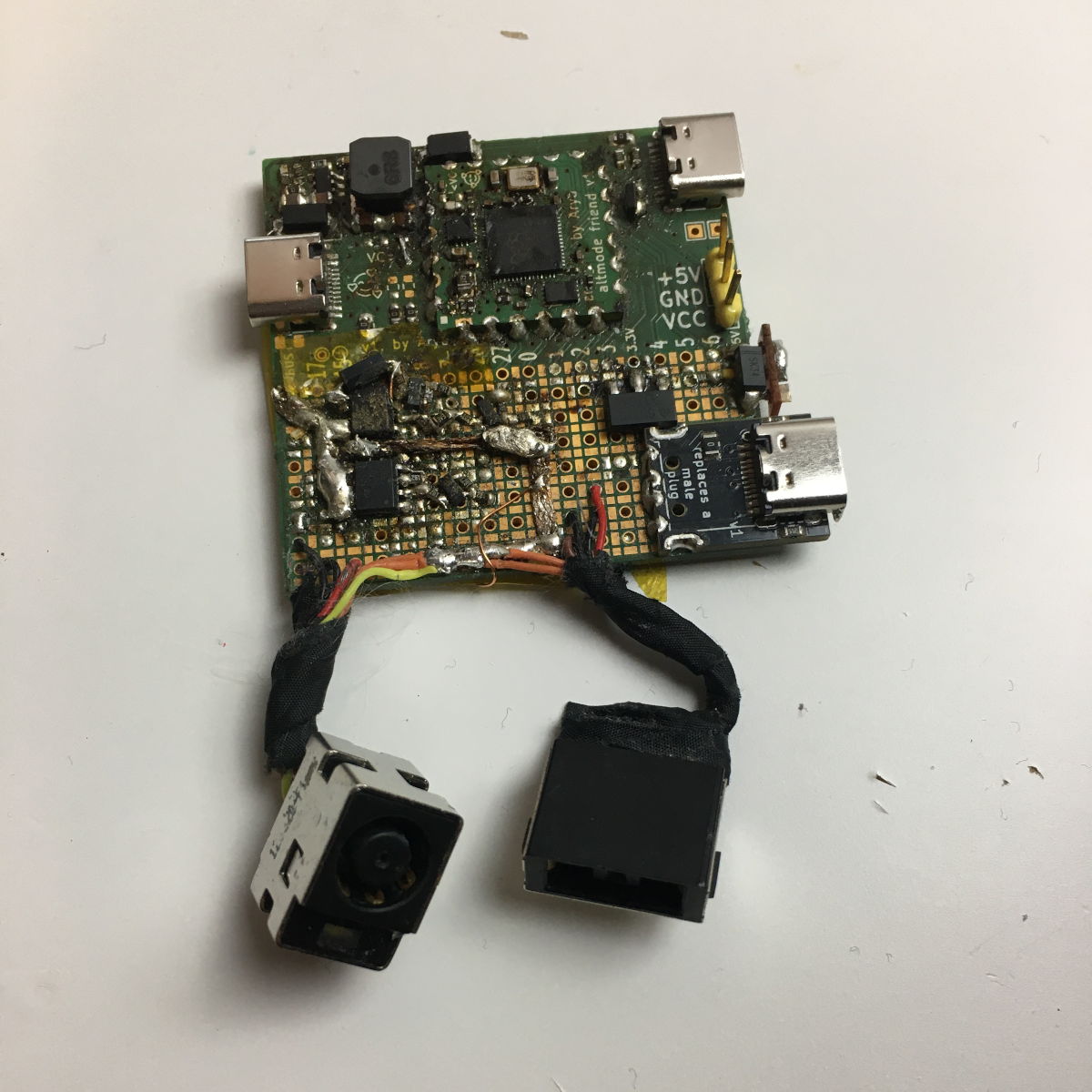
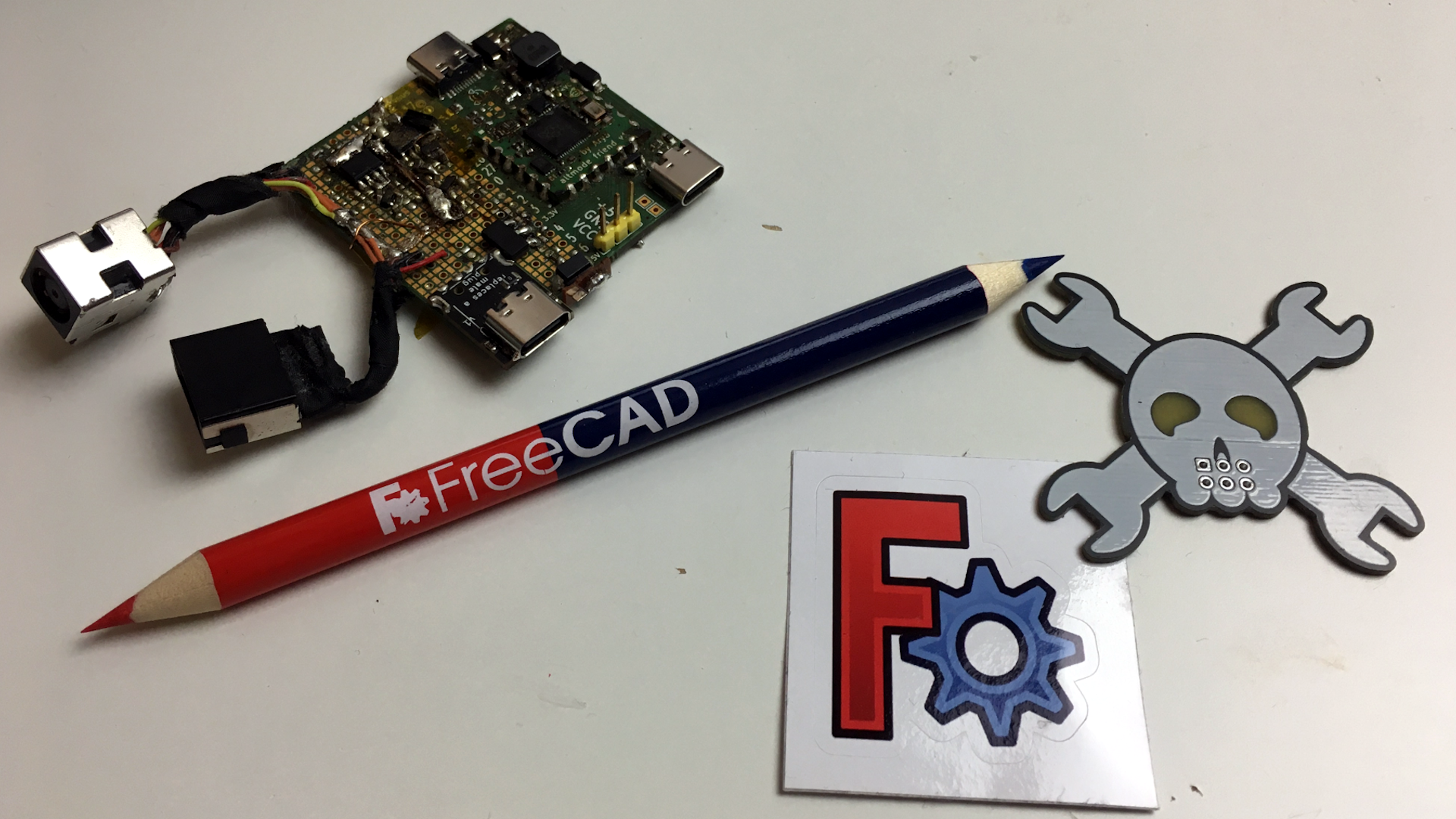
As motivation, I recently built a USB-C PSU board that uses a DC PSU and does the USB-C handshaking to provide 20 V to a laptop. It is currently my only 100 W USB-C PSU, and my 60 W PSU just died, which is why I now use this board 24/7. I have brought it on two different conferences so far, which has highlighted a problem – it’s a board with tons of exposed contacts, which means that it isn’t perfectly travel-friendly, and neither it is airport-friendly – not that I won’t try and bring it anyway. So, currently, I have to watch that nothing shorts out – given the board has 3.3 V close to 20 V at 9 A, it’s a bit of a worry.
This means I have to design some sort of case for it. I was taught SolidWorks in the half a year that I spent in a university, and honestly, I’m tired of the licensing and proprietary format stuff. When it comes to more hobbyist-accepted tools like Fusion360, I just don’t feel like exchanging one proprietary software for another. So, FreeCAD is the obvious choice – apart from OpenSCAD, which I know and love, but I don’t always want to think up fifteen variable names for every silly little feature. That, and I also want to fillet corners every now and then.
For a full-open-source workflow, today’s PCB is designed with KiCad, too. Let’s see about installing FreeCAD, and the few things you need to import a KiCad board file into FreeCAD.
Pick The Right Package And STEP Ahead
First, installation. On Windows, look for this guide. On Linux, there are a few ways to install FreeCAD – not all of them might work well for you. I’m using Ubuntu LTS, where the standard repository version is too old, and the PPA freecad-daily version was way too bleeding-edge for me. I’ve found that FreeCAD AppImages are a wonderful middle ground, and chances are, an AppImage is what you should get – it ought to work for you no matter the system. It’s a hefty executable alright, but it carries all its dependencies inside to make sure you have a smooth experience despite anything, and it’s a reasonably fresh FreeCAD snapshot.
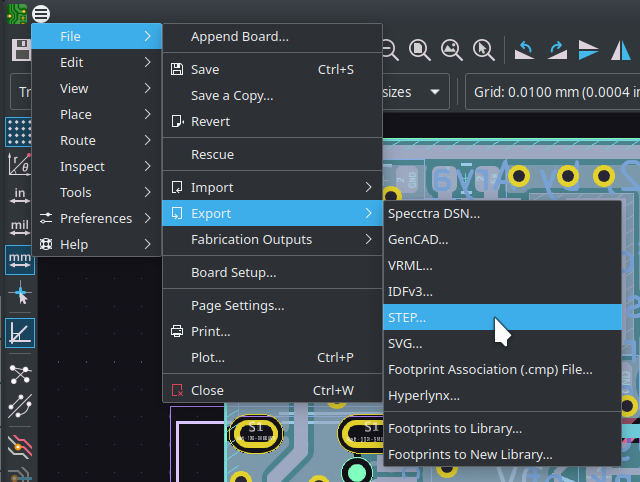
Today, we have a very simple PCB, the Altmode Friend devboard I developed as I went through writing the USB-C article series. KiCad has native STEP export – all it takes, as a rule, is going File=>Export=>STEP. Important – you want to have STEP models for all your components so that they can be exported too. KiCad libraries have both STEP and VRML models, and, VRML doesn’t work well for CAD. However, VRML models are picked by the default for KiCad components, perhaps because they’re more render-friendly. I’m not sure it’s necessary to do that anymore, but if your models don’t export together with your board, you might want to replace any .wrl model references with .step – I straight up edit the .kicad_pcb file in text editor and use a “.wrl to .step” search-replace for this. Got a .step model – now go File=>Import (Ctrl+I) in FreeCAD and load it, or, again, just drag&drop.
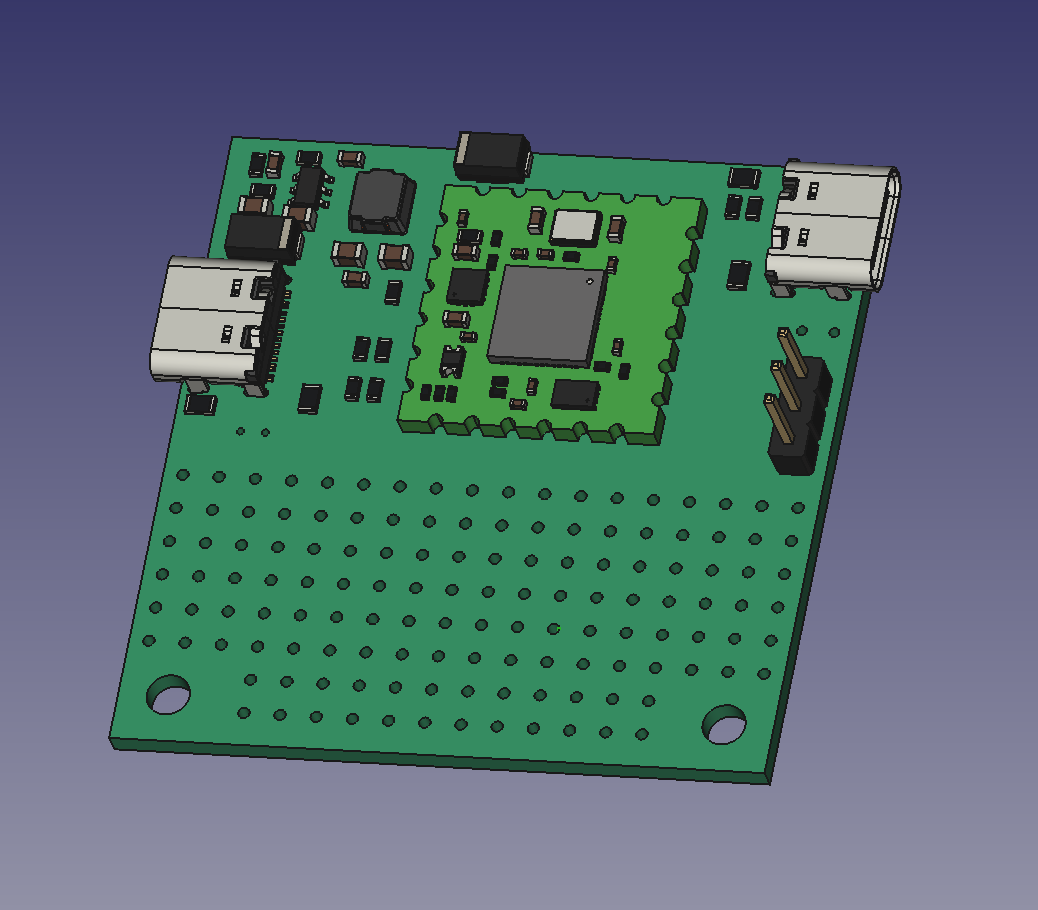
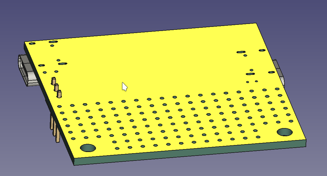
Yay, signs of life! There will not be any traces or silkscreen markings visible; you can check a KiCad-8-only option that exports them, but that will increase your file size quite a bit for barely any benefit, and the model will take a while to export&import, too. You will have a piece of green material in the exact shape of your board, PCB through-hole pads shown as holes (no plating), and the component 3D models attached on top of it, but that’s about it. Nevertheless, for mechanical design, this is more than enough.
Are any 3D models missing from your board? If the .wrl–.step conversion didn’t help, it might be that your footprint just doesn’t have a model associated, and if you can’t find a similar enough model in KiCad 3D libraries, you might need to download one. Check up with your parts’ manufacturers, for a start – places like Molex, Keystone, and many other manufacturers publish STEP files for their parts.
Alternatively, visit a place like GrabCad, make an account or bugmenot one, and treat yourself to the innumerable amount of models they have. Most of their models are either in STEP format or easily converted into STEP, and if it’s not, you might be able to convert it using FreeCAD itself. If you’ve found some part you need but it’s added to a more complex part (say, an LCD panel on an LCD breakout board 3D model) you can even use FreeCAD to yank only that part out of the multi-part STEP model, export that specific small part as a separate STEP, and load it into KiCad!
One addition you might want to know about – there’s also the KiCadStepUp plugin for FreeCAD that helps you import your KiCad boards, doing the STEP export automatically, and adding a whole bunch of improvements along the way. You can even edit the PCB outline as a FreeCad sketch, and then export it back into your KiCad PCB file with a single button! I’m not including the plugin in the article to make it as self-contained as possible, but it’s still very simple to install, and I recommend you check it out!
Interface Basics
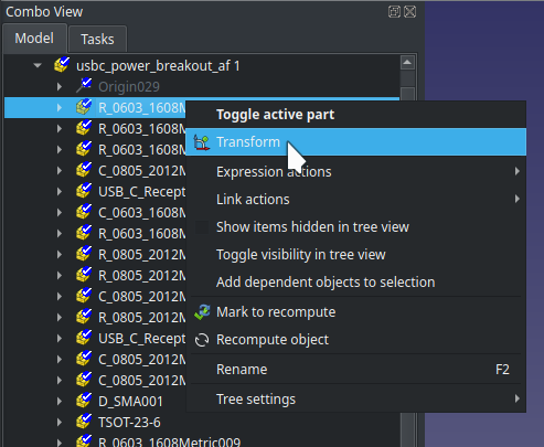
Transform – three coloured arrows will appear and let you move or rotate the board in 3D space. Click Esc if you want to exit the model movement menu – if you’re like me, you’ll accidentally go into it every now and then, so don’t let it startle you.
Want to move around the workspace, as you will usually do while CAD’ing? FreeCAD movement bindings might not be what you’re used to, so let’s make sure you know the current ones. And, as usual, if you want to design models lightning fast and without frustration, tooltips will show the keymaps to you when you hover over toolbar elements, and, you can check the keymaps using Tools=>Customize at any point!
Want to make any model disappear? Click on its entry in the tree and press Space – it will disappear from the model view and get greyed out in the tree. Alternatively, if you want to make it transparent, you can always exit any sketches, go into the Part workbench (this is important), right click the model, pick Appearance and move the transparency slider.
On the bottom is the commandline interface and log output. If something goes wrong, that’s where it will throw a bunch of red text at you – sometimes the red text will even be easy to understand! FreeCAD doesn’t tend to use dialog boxes, so if there’s a problem, expect it to appear in red in the commandline output. There are also timestamps, which make it easy to see if the problem disappears as you make changes. (A “clear output” button would be nice.)
If you’d like to try your hand at simple operations, here’s the first task – pick Transform (doubleclick in Combo View or right click => Transform) and use the arrows to rotate the the board parallel to the XY plane (plane formed by X and Y arrows), then move the board center to approximately axis center point (X 0 Y 0 Z 0 coordinates). This is very much not required, but it can help you while you design.
Two Workbenches, Same Purpose
On the top, you will see a dropdown, that likely says Start after you’ve booted up. This is also an important one – it has workbench switching. Click on it – you will notice Part, Part Design and Sketcher workbenches. You will invariably be using the Sketcher workbench, but as for Part and Part Design workbenches, you have to pick one of these two. My suggestion is that you go with Part, that’s what I’ve learned using so far, and it works wonders for me while not having some limitations of Part Design that would be my dealbreaker. Interested to learn more? Here’s a comparison on the FreeCAD wiki.

FreeCAD is community-sourced, a lot of people contribute a lot of different parts, thanks to its modular interface. A FreeCAD workbench is one such module that people can contribute – which is how it ended up with two workbenches for the same task. There are workbenches for all sorts of stuff, including one for KiCad import and one for OpenSCAD, and quite a few more. Who knows, maybe you will feel compelled to add a workbench at some point, too! But today, let’s start with a sketch.

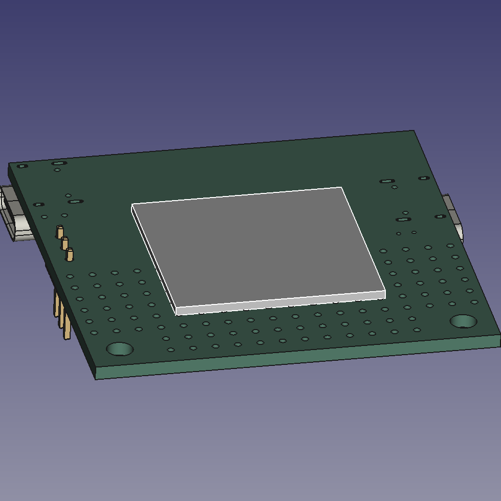
I’d start the sketch by drawing on the bottom of the PCB. Rotate the PCB so that its bottom is facing you, and click on it. That will highlight just one continuous surface on the board, the bottom surface. If you’ve accidentally selected the entire PCB as a block, all of it turning bright green, click on the background so that it gets deselected, then click once again on just the surface – that should simply select the face. Go to the workbench dropdown, select Sketcher, and press the New Sketch button. In the dialog that opens, simply press Ok or tap Enter – the default Plane face option is what you need.
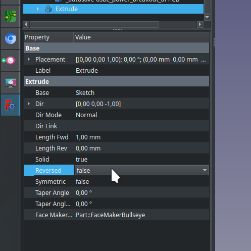
That brings you into the sketch drawing mode. Pick the rectangle tool and draw a random rectangle. Tap Esc to exit the sketch, go to Part workbench, then press the Extrude button. On the left, select extrusion length, and press “Ok”. See the extrusion? If it went into the direction you didn’t want, double click on the extrusion in model tree view, and at the bottom, look for the Reversed option; flip that.

This is the point at which I feel it’s safe to leave you alone with FreeCAD – any CAD-savvy hacker will learn the ropes from here, and if you’re looking to move away from something like Fusion360, or at least have a second option at your disposal, this is most of what you need to continue.
There’s one major thing I’ve found that’s unintuitive, that I feel like you should know about immediately. The tree view on the left panel will sometimes become as if unresponsive, and some menu items will be greyed out. If you find yourself battling that, you might have to exit the sketch you’re currently editing, or, if you have a sketch tool activated, you might have to press Esc on that to deactivate the tool. Another recommendation is – save early, save often; FreeCAD crashes like a proper CAD tool, less and less with every new version, but it is still a thing to watch out for.
Cool Features, Rough Edges, Friendly Tool
Next time, I want to show you how designing this case went, of course, and talk about things like external geometry. I’d also like to talk to you about a few things I’ve found, that you can keep in mind to ensure your FreeCAD workflow is as smooth as possible. I’ve also accumulated a list of things you want to avoid doing – we will talk about filleting, topo naming, general editing tips, and anything else that you personally think FreeCAD beginners should learn about. Make sure you leave a comment below if there’s anything you want to see discussed!