
![ethernet-for-hackers:-transformers,-macs-and-phys-[hackaday]](https://i0.wp.com/upmytech.com/wp-content/uploads/2024/03/172250-ethernet-for-hackers-transformers-macs-and-phys-hackaday.png?resize=800%2C445&ssl=1)
Ethernet For Hackers: Transformers, MACs And PHYs [Hackaday]

We’ve talked about Ethernet basics, and we’ve talked about equipment you will find with Ethernet. However, that’s obviously not all – you also need to know how to add Ethernet to your board and to your microcontroller. Such low-level details are harder to learn casually than the things we talked about previously, and today, we should pick up the slack.
You might also have some very fair question. What are the black blocks near Ethernet sockets that you generally will see on boards, and why do they look like nothing else you see on circuit boards ever? Why do some boards, like the Raspberry Pi, lack them altogether? What kind of chip do you need if you want to add Ethernet support to a microcontroller, and what might you need if your microcontroller claims to support Ethernet? Let’s talk.
Transformers Make The Data World Turn
One of the Ethernet’s many features is that it’s resillient, and easy to throw around. It’s also galvanically isolated, which means you don’t need a ground connection for a link either – not until you want a shield due to imposed interference, at which point, it might be that you’re pulling cable inside industrial machinery. There are a few tricks to Ethernet, and one such fundamental Ethernet trick is transformers, known as “magnetics” in Ethernet context.
Each pair has to be put through a transformer for the Ethernet port to work properly, as a rule. That’s the black epoxy-covered block you will inevitably see near an Ethernet port in your device. There are two places on the board as far as Ethernet goes – before the transformer, and after the transformer, and they’re treated differently. After the transformer, Ethernet is significantly more resillient to things like ground potential differences, which is how you can wire up two random computers with Ethernet and not even think about things like common mode bias or ground loops, things we must account for in audio, or digital interfaces that haven’t yet gone optical somehow.
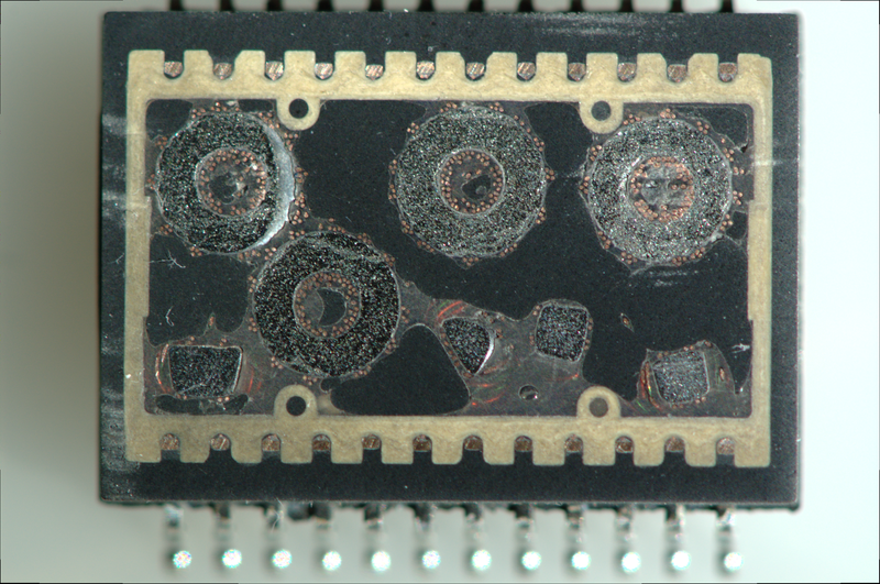
If you need some Ethernet transformers, you can buy them, but on a short notice, harvesting them is more than acceptable. Now, you have to be mindful, of course. One of the parameters of Ethernet transformers is a turns ratio, which can be different depending on the Ethernet chip in use. If you’re using magnetics with a different turns ratio, it might not work, or it might make the chip in question very unhappy; consult the datasheets!
There’s a lot to Ethernet magnetics, including tricks like capacitive coupling, where you can situationally avoid them altogether in very specific situations. We will go through the magnetic intricacies next time, but for now, they bring us to an interesting question. When a microcontroller says that it has an Ethernet port, what does it even imply? Is it enough to add a transformer, or would it need something else? It depends – let’s learn about it!
Two Different Meanings
There are two parts to Ethernet support in terms of hardware. First, there’s the MAC – that’s a block of hardware taking care of the Ethernet protocol logic. You can’t connect it directly to a transformer, but you can connect it to a PHY. The PHY works on the physical layer of Ethernet, it’s the piece of hardware that takes prepared Ethernet packets and translates them onto the wire. Often, MAC and PHY are just two different areas on a single chip, let’s say, in desktop and laptop Ethernet chips, but just as often they’re separate.
If your chip says that it supports Ethernet, that can mean two things – either it has a MAC and a PHY inside, or it only has a MAC. If the device is you’re playing with is a more networking-oriented chip, say, something like a Carambola or Onion Omega board, you will have the MAC+PHY combo – just wire up a transformer of some kind, even a magjack, and you are ready to go. If you’re looking at a microcontroller with Ethernet support though, say, an ESP32 or some STM, or the Pine64’s Ox64, it’s way more likely to just have a MAC, so you will have to add a compatible PHY to your circuit before you can start wiring up the transformer.
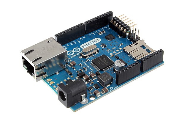
So, Ethernet support for your favourite piece of silicon might mean straightforward wireup, or it might require an extra chip. Thankfully, there’s no shortage of Ethernet-equipped designs to borrow things from – here’s the Olimex ESP32 design for instance, open-source and giving you a circuit known to work in production. Just be careful taking PoE information from Olimex ESP32 boards – their PoE implementation, is, let’s say, situationally useful, which is why there’s warnings on the page about USB programming, but it’s a great start still!
A Sprinkle Of Resistors
Of course, there are plenty of schematics and reference designs to copy from, and if you do, you might wonder – what are the passives shown inside a magjack schematic, or visible on a board right next to the magnetics? Chances are, you are looking at the Bob Smith termination.
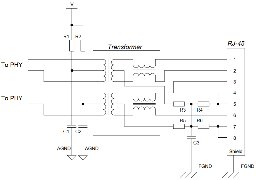
Bob Smith termination is something you do for unterminated Ethernet pairs at 10/100Mbps, which you will likely have to work with. It shunts the unused two pairs, both connecting the two wires of each pair together so that the entire pair is treated as a single wire, but also brings the pair to a certain voltage so that any noise induced onto it over the length don’t overlay onto signals on the actually used pairs. Also, this is one of the things you might burn out if you plug a passive PoE-enabled cable – the resistors will shunt the DC path; which is why PoE-compatible magnetics add extra capacitors in series with each resistor.
On the other side, you will see pullup resistors on the center taps of the active pairs, and capacitors to ground. Omitting either of these will cause your devices to get unhappy, so if your PHY releases magic smoke, or if your Ethernet link glitches out every now and then, you will look back and wish you added them – and it costs nothing to add footprints for them that you can populate later.
Next time, I’d like to show you open-source designs and walk you through a few of them, pointing out things that are there for a reason that you might not be aware of. There are things like isolation perimeters, shield connection, Bob Smith termination values, polarity swaps and PoE tap ways, that you likely want to talk about, and I will highlight appnotes that you’d benefit from reading through, too!
Featured image: “10base-T” by [gratuit]