
![displayport:-hacking-and-examples-[hackaday]](https://i0.wp.com/upmytech.com/wp-content/uploads/2024/05/184195-displayport-hacking-and-examples-hackaday-scaled.jpg?resize=800%2C445&ssl=1)
DisplayPort: Hacking And Examples [Hackaday]
So far, I’ve talked about why DisplayPort is the future, introduced the basics of how to work with it on the hacker level, took apart and tamed the DisplayPort altmode, and recently, went through the eDP (embedded DisplayPort) display technology. This time, I want to give you a project library to reference, so that your hacking goes as smoothly as possible – real-world examples of open-source DisplayPort boards, a few boards I’ve worked on, part numbers, and whatever other information you might need.
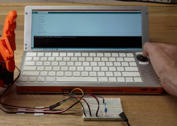
Over the past few years, I’ve noticed that a non-zero amount of cyberdeck builders buy eDP screens with HDMI converter boards on Aliexpress, then connect them to SBCs using USB-C to HDMI adapters, or ignore the onboard eDP port; even this super cool Framework-based cyberdeck has done that! I get that it’s the simplest option, but I do believe that you ought to know how to improve it. The issue is that this double-conversion decreases the battery life significantly by burning two extra ASICs doing video conversion back and forth. Every hour of battery life matters in a cyberdeck, doubly so if it’s based on a low-power device already – you could easily cut your battery life in half if you’re not careful!
With these projects and references in your arsenal, my aim is that DisplayPort becomes way more comfortable for you to work with. Thankfully, there are quite a few projects to reference by now – let’s delve in.
Right out of the gate – are you looking for an SBC with DisplayPort support? The BoardDB website, a database of single-board computers, has a DisplayPort filter – click this link with the filter already enabled and browse through.
Gateway Tablets
Perhaps the most omnipresent open-source DisplayPort project is the Adafruit adapter for iPad Retina displays. When iPad Retina displays became available to hackers, as far as I can tell, it was [Andrzej] who discovered that they were using the eDP interface, and figured out that you could easily convert it to DisplayPort. Eventually, that led to Adafruit making an adapter board they could mass-produce – which is one of the best outcomes for such an idea! We’ve seen proprietary boards for these displays being sold since then, even with USB-C DP altmode support – but the Adafruit board is open-source, which makes for a way better start, more so given they have cool tutorials to go with it.
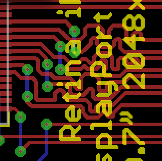
There’s many things you can learn from this board, and some things you shouldn’t. Well, one thing you shouldn’t – the trace routing on the Adafruit board is seriously puzzling, even though it undeniably works. However, it gives you an example on how to drive a bare backlight – something you still might have to do when it comes to tablet displays. Oh, and there’s an ATTiny for managing the PWM input of the backlight driver, and a few buttons – if you’re making your own eDP adapter and you need a backlight driver controller, you could do worse than yanking their ATTiny firmware and schematic.
Now, this has kickstarted a fair bit more eDP hacking – like this Retina adapter we’ve covered a few years ago, there’s been other boards for other eDP displays, too; and, iPad screens are still here and available for purchase. The bottom line is that wiring up an eDP display is easy, and it might make your cyberdeck all that more practical. Now, a Raspberry Pi with a DisplayPort connection would be awesome to have, but I suppose RPF’s allegiance to Broadcom’s allegiance to HDMI makes it unlikely – until someone figures out an accessible and Pi-compatible DSI-DP converter, or at least, I can dream.
Laptop Panel Handling And Connectors
Here’s something I no longer have to dream about – an adapter from DisplayPort to different eDP connectors, that [WifiCable] and I have recently designed. Remember – eDP displays only use two different connectors, and, there’s an abundance of FPC-to-eDP cables on Aliexpress and other Eastern marketplaces, so you might only need to add an FFC connector onto your board. As for pinouts, this adapter supports four different eDP pinouts with three connectors, including the pinout of the Asus ROG Ally display, and it handles touch-enabled displays too.
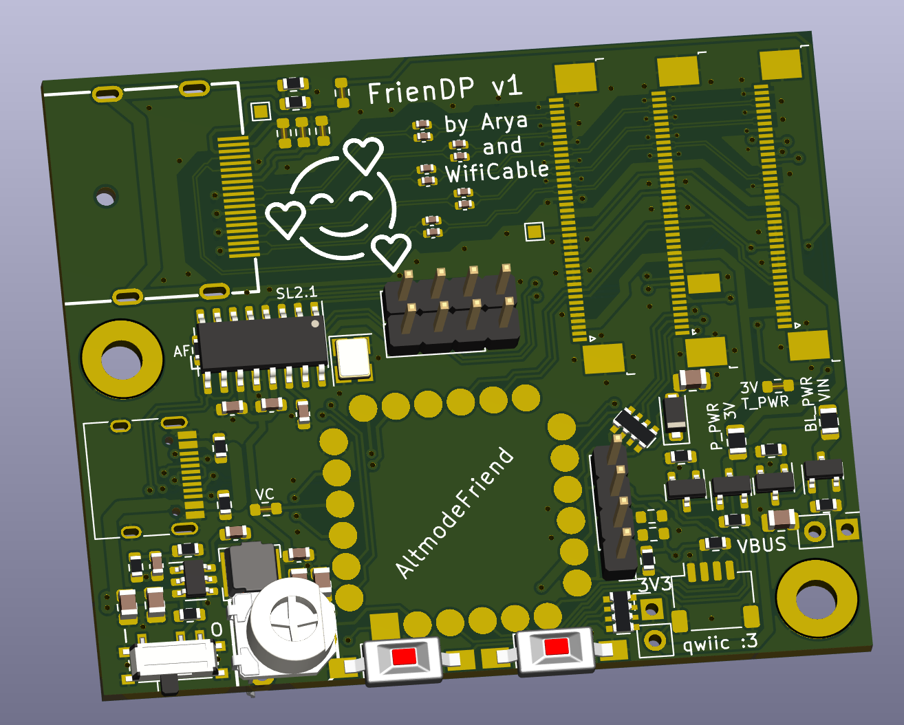
From this board’s files, you can get things like the eDP panel pinouts you can copy-paste into your KiCad project, as well as footprint and symbol for a DisplayPort connector. Now, to be clear, we got the footprint and symbol from LCSC. You can find DisplayPort sockets on Mouser and Digikey, but LCSC is that much cheaper.
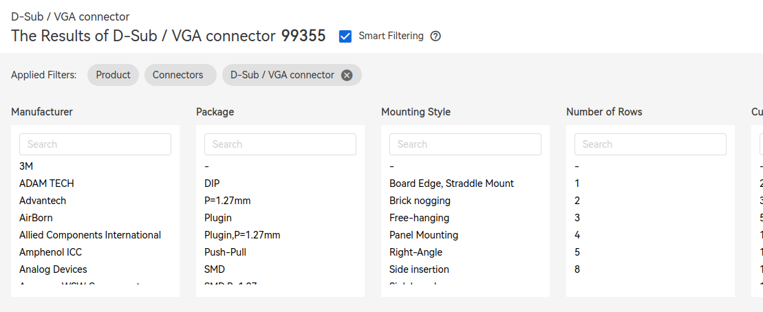
Actually locating DisplayPort parts on LCSC is tricky, but gets way easier after you follow some simple rules. First rule is – don’t only check the DisplayPort category, since manufacturers seem to often ignore it; check the D-Sub/VGA connector category, too. Second rule is – do not touch absolutely any filters, make sure all of them are disabled – you have to do this because filters on LCSC are deeply broken; the only thing you can touch is “In Stock”, so only check that. Third rule is – set “items per page” to 100, for your own sanity’s sake. Maybe complain to them so that they bring back the 500 option, because I’m personally tired of doing that, only for them to again limit it back to 100 a month later.
Also, here’s a DisplayPort socket on LCSC, and another, and another, and here’s a miniDisplayPort socket; please don’t buy them all out, thanks. There’s no shortage of chips either, just that they can be a bit tricky to find. For instance, do you want high-speed muxes? Here’s two independent KiCad projects who do DisplayPort “one port to many ports” KVM-style muxing; this one just does DP and this one also supports USB. It’s no MST, but if you want to switch between screens or DisplayPort sources, it’s a pretty viable solution! In general, if you look up "AUX+" kicad in the GitHub search bar, you can find out about some fun boards, and even find ICs you might’ve otherwise missed.
As an aside, if your DP transmitter does DP++, the MXM immobilizer project from [WifiCable] gives you a reference implementation that supports both DisplayPort and HDMI/DVI backwards compatibility mode on your connector. This one has been taken from working laptop schematics; that said, this design hasn’t been tested. This PCIe-MXM design was tested, though, and even though the license is super restrictive, you should still be able to check schematics, especially if you go to the commit before the author deleted the KiCad port of this adapter.
USB-C DP Altmode And Motherboard Hacking
Here’s another design you can make use of: a USB-C to eDP converter. I’ve recently been finishing bringup of this board, and while I got a little stuck on making the firmware perfect before making it actually work, the AUX connection has indeed after bodging two resistors onto it, which are now integrated into the design. The only area yet unexplored are the main DP lanes, which, I’m sure, have no problems at all and will work wonderfully first try as soon as I figure out the right VDM. I’ve partially covered this design in the altmode taming article and talked some about DisplayPort USB-C muxes, but I haven’t published it yet at that point, and that was long overdue, so here you go.

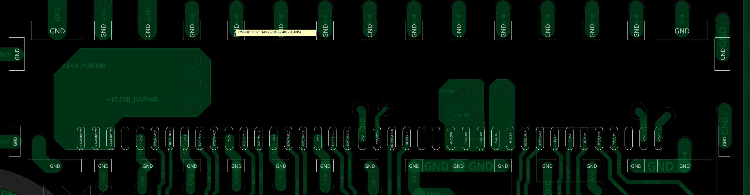
This connector may look tricky to solder onto your board, what’s with the pads being fully hidden, and it is tricky to both solder and repair, but it’s a pretty suitable choice if you are decent at stenciling. Also, thanks to Framework as of recently, you can buy their cables separately– they’re locked into the 40-pin high-res pinout and you can’t easily change that, but you could definitely add an adapter if needed. If you’re looking for a fancy connector that still supports more hobbyist-oriented soldering methods, however, a good middle ground is using the I-PEX connector that eDP laptop displays themselves use, and then finding a male-male cable with microcoax wires on either Aliexpress or Digikey.
Framework’s connector is the connector you will want to use if you want to connect an arbitrary display to a Framework mainboard, too, and it’s not easy to make custom cables for it. That’s not an uncommon situation – some of the SBCs with DisplayPort in the SBC database list I’ve linked, will too have it on a connector that ain’t easy to work with; watch out! Fortunately, even here, you could use the Framework’s cable, plug it into the Framework motherboard, and put an I-PEX 40-pin high-res pinout socket on your adapter board – that’s what I’m currently doing for a small and yet-unfinished project of mine. Otherwise, if you need the touchscreen signals that Framework cable doesn’t pass through, you could do a breakout with a male-male cable; as long as you’re okay spending $50 on a cable, that is.
Capacitors, Resistors, And PDFs
When you see some of the open-source boards, you might see series capacitors, perhaps, even pullup or pulldown resistors on the AUX line, too. They’re something I ought to have expanded upon in the Under The Hood installment, but the second best time is to do it now, before the boards might leave you confused. An official DisplayPort spec will help with both of these – you can find it easily enough by looking up DP-1.2.pdf; I couldn’t find higher version specs PDF names for you since they’re not public. There’s no spec for embedded DisplayPort that I could find, and it’d be wonderful to take a look, so if someone has it handy, please do let me know!
You need series capacitors for both the AUX link (1.2 spec page 329) and the main link pairs (page 362); range is 75 to 200 nF, so regular 100 nF will do. The 0402 package is preferred, but 0603 is possible. Main link capacitors are only required on transmitter (source = upstream) end, but you can put them on the receiver (sink = downstream) end too if you’d like. Remember that stacking capacitors in series causes the overall capacitance to decrease in the same exact way that resistance decreases when you stack resistors in parallel, so you might not want to overdo it.
The AUX channel is a differential pair – as you might remember, it’s used for monitor parameter querying, link training, configuration, and things like audio. Just like USB2, it’s pseudodifferential – there’s resistors that sometimes have to be used for your device to be detected, or for the bus to be properly biased to work. The transmitter pulls AUX+ down and AUX- up to 3.3V, the receiver pulls AUX- up and AUX+ down. Oh, and remember HPD? It needs a 100k-ish pulldown on the device side (page 327).
Do you need either capacitors or resistors for a regular DP adapter? Likely not – a DisplayPort source will integrate them, and your display might, too. However, they might be useful if you’re working on a USB-C adapter or adding muxes to the equation, and it helps to know that they’re sometimes required.
DisplayPort is not always faultless – for instance, you might find out that your SBC’s DisplayPort driver has not been tested with lane widths less than four, as [Timon] found out during the [Damn Linux Tablet] project. However, it’s still a great option for your displays, and one you deserve to be able to work with – there’s no shortage of DisplayPort hardware around us. May these designs and references help you in your own DisplayPort forays, no matter what you might be building.
I thank [WifiCable] for help in compiling the materials and links for this article!