
![beyond-the-basics:-exploring-exotic-scope-trigger-modes-[hackaday]](https://i0.wp.com/upmytech.com/wp-content/uploads/2023/12/158964-beyond-the-basics-exploring-exotic-scope-trigger-modes-hackaday-scaled.jpg?resize=800%2C445&ssl=1)
Beyond the Basics: Exploring Exotic Scope Trigger Modes [Hackaday]
Will Rogers once said that veterinarians are the best doctors because their patients can’t tell them where it hurts. I’ve often thought that electronic people have a similar problem. In many cases, what’s wrong with our circuits isn’t visible. Sure, you can visually identify a backward diode, a bad solder joint, or a blown fuse. But you can’t look at a battery and see that it is dead or that a clock signal isn’t reaching some voltage. There are lots of ways to look at what’s really going on, but there is no substitute for a scope. It used to be hard for the average person to own a scope, but these days, it doesn’t require much. If you aren’t shopping for the best tech or you are willing to use it with a PC, oscilloscopes are quite affordable. If you spend even a little, you can now get scopes that are surprisingly capable with features undreamed of in years past. For example, many modern scopes have a dizzying array of triggering options. Do you need them? What do they do? Let’s find out.
I’ll be using a relatively new Rigol DHO924S, but none of the triggering modes are unique to that instrument. Sometimes, they have different names, and, of course, their setup might look different than my pictures, but you should be able to figure it out.
What is Triggering?
In simple terms, an oscilloscope plots time across the X-axis and voltage vertically on the Y-axis. So you can look at two peaks, for example, and measure the distance between them to understand how far apart they are in time. If the signal you are measuring happens repeatedly — like a square or sine wave, for example — it hardly matters which set of peaks you look at. After all, they are all the same for practical purposes.
The problem occurs when you want to see something relative to a particular event. Basic scopes often have level triggering. They “start” when the input voltage goes above or below a certain value. Suppose you are looking at a square wave that goes from 0 V to 5 V. You could trigger at about 2.5 V, and the scope will never start in the middle of a cycle.
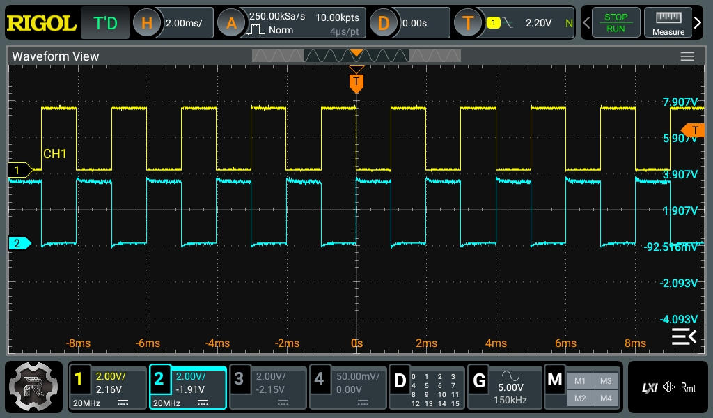
Digital scopes tend to capture data before and after the trigger, so the center of the screen will be right on an edge, and you’ll be able to see the square waves on either side. The picture shows two square waves on the screen with the trigger point marked with a T in the top center of the display. You can see the level in the top bar and also marked with a T on the right side of the screen.
What happens if there are no pulses on the trigger source channel? That depends. If you are in auto mode, the scope will eventually get impatient and trigger at random. This lets you see what’s going on, but there’s no reference. If you are in normal mode, though, the scope will either show nothing or show the last thing it displayed. Either way, the green text near the top left corner will read WAIT until the trigger event occurs. Then it will say T’D.
What’s Wrong with Edge Triggering?
Edge triggering — triggering when voltage goes above or below some trigger point — is tried and true. Why go beyond that? Well, the picture above is a little misleading. Watch the video below and see if you notice anything odd.
The square waves are as they appear in the still picture, but there is a little flickering. That’s a clue that something else is going on, but what? Well, using different triggers, we can investigate further.
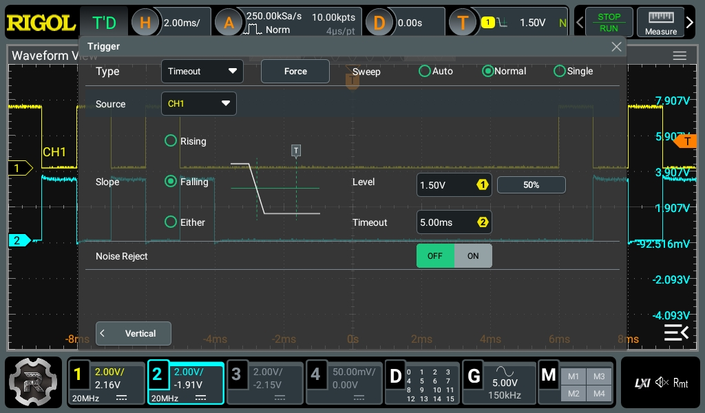
Let’s speculate that one of the signals may be getting stuck briefly. Maybe that’s a sign that something is wrong. Or maybe it is supposed to be like that, and we want to verify it. You can set up a timeout trigger.
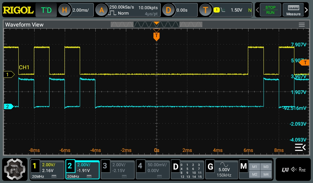
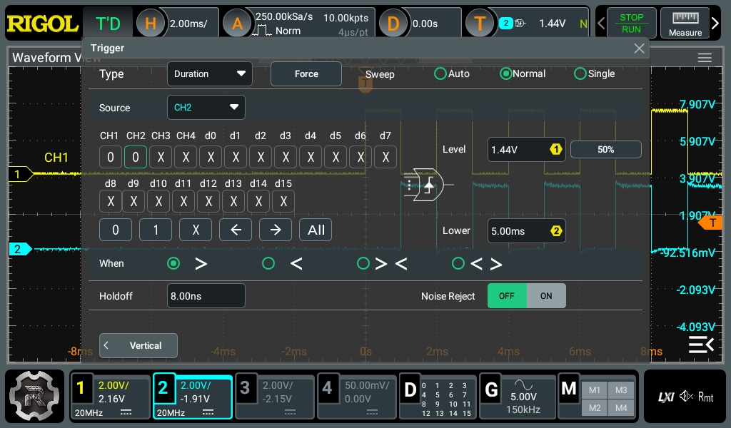
This timeout trigger tells the scope that if the signal stays low after a falling edge for too long, it should trigger. You can pick the level — the voltage that indicates a falling edge and the timeout. Note the scope is in normal mode, so nothing will show until the scope triggers (or, at least, nothing will update). The result?
Turns out the signal source pauses just a little bit every so often. Hard to see in the video, but crystal clear now that the trigger is set to detect it.
More Triggers
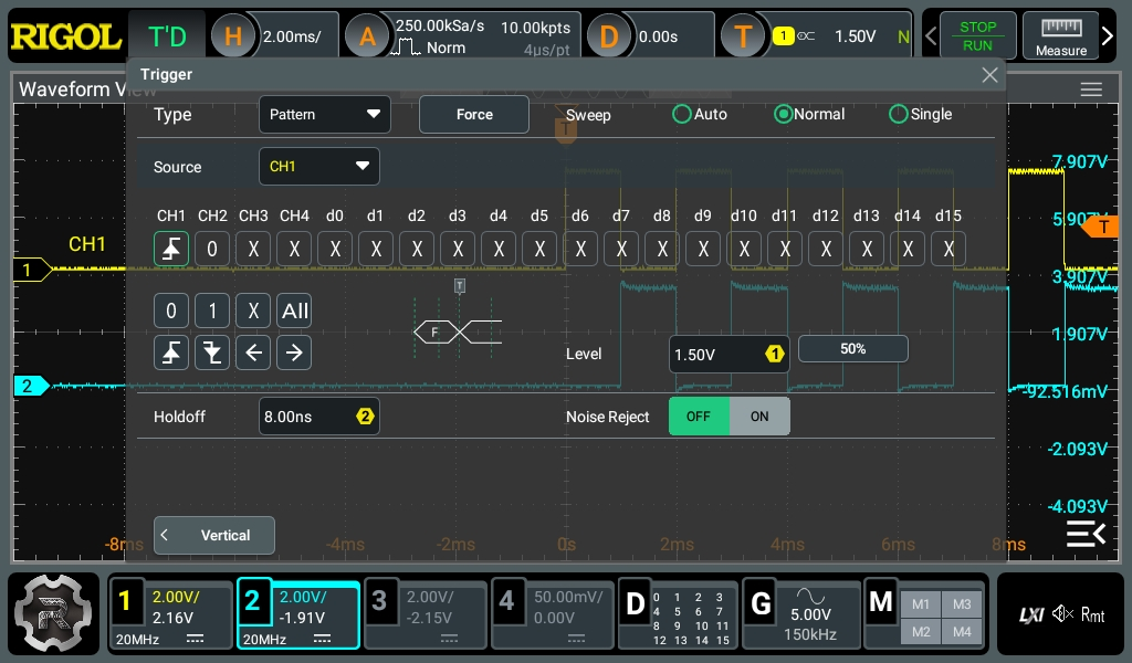
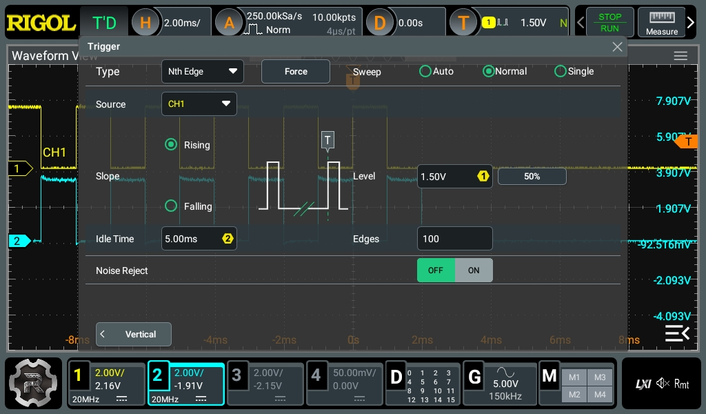
There are other ways to detect this pattern, too, especially once you know what to look for. For example, you can use the delay trigger to note when there is a long gap or look for a pattern where both signals are low. You can even move where the trigger occurs by modifying the timeout. Finally, since the event occurs every 100 pulses, you can simply count pulses. That’s sort of cheating, but if you had some other thing you wanted to sample on a specific number of pulses, it would be worthwhile.
You can see the different configurations below. The output screen will look more or less the same, with just slight variations on exactly where the trigger point occurs.

Triggers on Data
Most modern scopes have — at least as an option — a way to decode data using different protocols. For example, the scope can interpret RS232, CAN bus, I2C, SPI, and so on. It isn’t uncommon to have a way to trigger when specific data appears on a decoded bus.
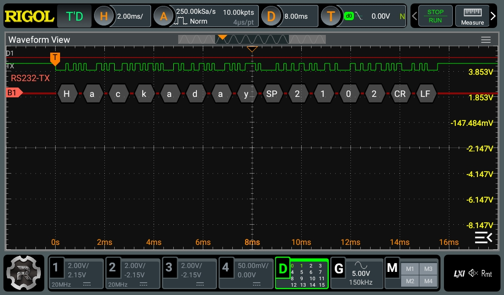
Sometimes, you really do want to see the bus, but you might also want to look at some other signals when the bus triggers. The example in the images shows a serial port sending out “Hackaday” and a count. The scope is triggering on a capital “H.” While the scope input, in this case, is digital, this works on an analog signal, too.
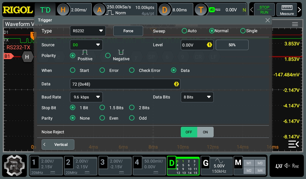
Each mode will be a little different, but, in general, you’ll need to set the threshold if you are using an analog input and if the data is inverted or not. You’ll also provide any specific parameters for the protocol, like baud rate and number of bits, of course. In this particular case, the scope can trigger on data or certain conditions like framing errors or a start bit.
Of course, each scope is different, and each protocol will be slightly different, too. Sometimes, the biggest value of this is not so much looking at the data stream but, instead, using the data trigger to look at other, possibly analog signals simultaneously.
Not Just for Digital
So far, the trigger data has been more or less digital pulses. However, sophisticated triggers exist for things like slope. To work with that, I used a little extra circuitry. Next time, we’ll look at runt triggers, slope triggers, and another digital trigger for setup and hold violations.
All of these various waveforms were created using a few different C++/Arduino programs on a Raspberry Pi Pico. You can pick up the code in a Gist if you want to try it out for yourself.