
![a-rotary-encoder:-how-hard-can-it-be?-[hackaday]](https://i0.wp.com/upmytech.com/wp-content/uploads/2022/04/61849-a-rotary-encoder-how-hard-can-it-be-hackaday.jpg?resize=800%2C445&ssl=1)
A Rotary Encoder: How Hard Can It Be? [Hackaday]

As you may have noticed, I’ve been working with an STM32 ARM CPU using Mbed. There was a time when Mbed was pretty simple, but a lot has changed since it has morphed into Mbed OS. Unfortunately, that means that a lot of libraries and examples you can find don’t work with the newer system.
I needed a rotary encoder — I pulled a cheap one out of one of those “49 boards for Arduino” kits you see around. Not the finest encoder in the land, I’m sure, but it should do the job. Unfortunately, Mbed OS doesn’t have a driver for an encoder and the first few third-party libraries I found either worked via polling or wouldn’t compile with the latest Mbed. Of course, reading an encoder isn’t a mysterious process. How hard can it be to write the code yourself? How hard, indeed. I thought I’d share my code and the process of how I got there.
There are many ways you can read a rotary encoder. Some are probably better than my method. Also, these cheap mechanical encoders are terrible. If you were trying to do precision work, you should probably be looking at a different technology like an optical encoder. I mention this because it is nearly impossible to read one of these flawlessly.
So my goal was simple: I wanted something interrupt driven. Most of what I found required you to periodically call some function or set up a timer interrupt. Then they built a state machine to track the encoder. That’s fine, but it means you eat up a lot of processor just to check in on the encoder even if it isn’t moving. The STM32 CPU can easily interrupt with a pin changes, so that’s what I wanted.
The Catch
The problem is, of course, that mechanical switches bounce. So you have to filter that bounce either in hardware or software. I really didn’t want to put in any extra hardware more than a capacitor, so the software would have to handle it.
I also didn’t want to use any more interrupts than absolutely necessary. The Mbed system makes it easy to handle interrupts, but there is a bit of latency. Actually, after it was all over, I measured the latency and it isn’t that bad — I’ll talk about that a little later. Regardless, I had decided to try to use only a pair of interrupts.
In Theory
In theory, reading an encoder is a piece of cake. There are two outputs, we’ll call them A and B. When you turn the knob, these outputs send out pulses. The mechanical arrangement inside is such that when the knob is turning in one direction, pulses from A are 90 degrees ahead of the pulses from B. If you turn the other way, the phase is reversed.

 100vw, 800px”></p>
<p>People usually think of the pulses as going positive, but most real encoders will have a contact to ground and a pull up resistor, so actually, the outputs are often high when nothing is happening and the pulses are really low pulses. You can see that in the diagram when no one is turning the knob, there is a long stretch of high signal.</p>
<p>Note on the left side of the diagram that the B signal drops before the A signal every time. If you sample B at the falling edge of A, you will always get a 0 in this case. The width of the pulses depends on the speed you turn, of course. When you turn the other way, you get the case on the right side of the diagram. Here, the A signal goes low first. If you sample at the same point, B is now 1.</p>
<p>Note there is nothing magic about A, B, or the clockwise and counterclockwise labels. All it really means is “one way” and “the other way.” If you don’t like how the encoder is moving you can just swap A and B or swap it in software. I just picked those directions arbitrarily. Usually, channel A is supposed to “lead” in the clockwise direction, but it also depends on the edge you measure and how you connect everything. In software, you generally add one to a count for one direction and subtract for the other direction to get an idea of where you are over time.</p>
<p>There are many ways you can read this sort of input. If you are sampling it, it is pretty easy to build a state machine from the two bits and process it that way. The output forms a gray code so you can throw away bad states and bad state transitions. However, if you are sure about your input signal, it can be much easier than that. Just read B on one edge of A (or vice versa). You could verify the other edge if you wanted a little more robustness.</p>
<h2>In Practice</h2>
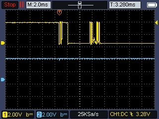
<p>Unfortunately, real mechanical encoders don’t look like the above diagram. They look more like this:</p>
<p><a href=)
This leads to a problem. If you are interrupting on both edges of input A (the upper trace on the scope), you will get a series of pulses at both edges. Notice that B is in different states at each edge of A, so if you get an even number of pulses in total, your total count will be zero. If you are lucky, you might get an odd number in the right direction. Or you might get the wrong direction. What a mess.
But on the sampling edge of A, B is rock solid. The lower trace on the scope looks like a straight line because all the B transitions are off the screen at that scale. That’s the secret to easily debouncing an encoder. When A is changing, B is stable and vice versa. Since it is a gray code, that makes sense, but it is the insight that makes a simple decoder possible.
The Plan
So the plan is to notice when A goes from high to low and then read B. Then ignore A until B changes. If you want to monitor B, of course, it has the same problem so you have to lock it to A which is stable at the change. In my case, I didn’t want to use two more interrupts so I follow this logic:
- When A falls, record the state of B and update the count. Then set a lock flag
- If A falls again, if the lock flag is set or B has not changed, do nothing.
- When A rises, if B has changed, record the state of B and clear the lock flag.
That means in the scope trace above, the first dip in the top trace causes us to read B. After that, none of the transitions on the screen will have any effect because B has not changed. The rising edge off the screen that occurs after B has had a noisy high to low transition will be the one that unlocks the algorithm.
The Problem
There is a problem, though. The whole scheme relies on the idea that B will be different on a true rising edge for A compared to a falling edge. There is one case where B doesn’t change but we still want to accept the A edge. That’s when you change directions. If you monitored B, that would be easy to solve, but that’s more code and two more interrupts. Instead, I decided that for a person twisting a knob, if you wildly twist in different directions very quickly, you won’t even notice that one or two clicks of the encoder went the wrong way. What you will notice is if you make a fine adjustment and then twist the other way deliberately.
 100vw, 710px”></p>
<p>When you think you know the previous state of B and nothing has changed in a while (like a few hundred milliseconds) the code will reset its idea of B to unknown so that the next B signal will be considered valid no matter what.</p>
<p>I used the <code>Kernel::Clock::now</code> feature from Mbed. It isn’t clear if you are supposed to call that from an interrupt service routine (ISR), but I am and it seems to work without problems.</p>
<p>The only other issue is to make sure the count doesn’t change in the middle of reading it. I disabled interrupts around the read just to make sure.</p>
<h2>The Code</h2>
<p>You can find the code on <a href=)
<
pre class=”brush: cpp; title: ; notranslate”>
void Encoder::isrRisingA()
{
int b=BPin; // read B
if (lock && lastB==b) return; // not time to unlock
// if lock=0 and _lastB==b these two lines do nothing
// but if lock is 1 and/or _lastB!=b then one of them does something
lock=0;
lastB=b;
locktime=Kernel::Clock::now()+locktime0; // even if not locked, timeout the lastB
}
// The falling edge is where we do the count
// Note that if you pause a bit, the lock will expire because otherwise
// we have to monitor B also to know if a change in direction occurred
// It is tempting to try to mutually lock/unlock the ISRs, but in real life
// the edges are followed by a bunch of bounce edges while B is stable
// B will change while A is stable
// So unless you want to also watch B against A, you have to make some
// compromise and this works well enough in practice
void Encoder::isrFallingA()
{
int b;
// clear lock if timedout and in either case forget lastB if we haven’t seen an edge in a long time
if (locktime<Kernel::Clock::now())
{
lock=0;
lastB=2; // impossible value so we must read this event
}
if (lock) return; // we are locked so done
b=BPin; // read B
if (b==lastB) return; // no change in B
lock=1; // don’t read the upcoming bounces
locktime=Kernel::Clock::now()+locktime0; // set up timeout for lock
lastB=b; // remember where B is now
accum+=(b?-1:1); // finally, do the count!
}
Setting up the interrupt is easy because of the InterruptIn class. This is like a DigitalIn object but has a way to attach a function to the rising or falling edge. In this case, we use both.
Latency
I wondered how much time it took to process an interrupt on this setup, so that code is available if you set #define TEST_LATENCY 1. You can see a video of my results, but TLDR: It took no more than 10 microseconds to get an interrupt and often about half of that.
Getting the encoder right was a little harder than I thought it would be, but mostly because I didn’t want to process more interrupts. It would be simple enough to modify the code to watch the B pin relative to the A pin and have a true understanding of the correct state of B. If you try that modification, here’s another idea: by measuring the time between interrupts, you could also get an idea of how fast the encoder is turning, which might be useful for some applications.
If you want a refresher on gray code and some of where it is useful, we’ve talked about it before. If all this sounds oddly familiar, I used an encoder on an old version of Mbed in 2017. In that case, I used a canned library that periodically polled the inputs on a timer interrupt. But like I say, there’s always more than one way to make stuff like this happen.
[Headline image: “Rotary Encoder” by SparkFunElectronics, CC BY 2.0. Awesome.]