![a-field-guide-to-the-north-american-substation-[hackaday]](https://i0.wp.com/upmytech.com/wp-content/uploads/2024/08/206660-a-field-guide-to-the-north-american-substation-hackaday.jpg?resize=800%2C445&ssl=1)
A Field Guide to the North American Substation [Hackaday]
Drive along nearly any major road in the United States and it won’t be long before you see evidence of the electrical grid. Whether it’s wooden poles strung along the right of way or a line of transmission towers marching across the countryside in the distance, signs of the grid are never far from view but often go ignored, blending into the infrastructure background and becoming one with the noise of our built environment.
But there’s one part of the electrical grid that, despite being more widely distributed and often relegated to locations off the beaten path, is hard to ignore. It’s the electrical substation, more than 55,000 of which dot the landscape of the US alone. They’re part of a continent-spanning machine that operates as one to move electricity from where it’s produced to where it’s consumed, all within the same instant of time. These monuments of galvanized steel are filled with strange, humming equipment of inscrutable purpose, seemingly operating without direct human intervention. But if you look carefully, there’s a lot of fascinating engineering going on behind those chain-link fences with the forbidding signage, and the arrangement of equipment within them tells an interesting story about how the electrical grid works, and what the consequences are when it doesn’t.
From The Ground Up
The most basic function of a substation is to transform voltages, either stepping up the voltage from the point of production for efficient transmission over long distances, or stepping voltages down from transmission systems to feed regional or local distribution systems. That makes substations conceptually simple, but as is always the case in engineering, the details are where things get interesting.
While the equipment mounted above the ground is the easiest part of a substation to observe, what you don’t see is arguably far more important, at least in terms of safety. A note to frame the discussion: we’ll be concentrating on open-air substations, rather than substations that are inside a structure, which are an important and interesting part of the grid, but harder to observe casually.
Substations must have an extensive grounding system, both for worker safety and to provide the needed neutral reference. Most substations use a grid of thick copper conductors buried just below the surface, tied together at regular intervals to ground rods extending 25 feet (7 meters) or more into the soil below. Horizontal and vertical conductors are tied together with exothermically welded connections or cold-forged fittings to form low-impedance electrical connections between every element of the grid. The grounding grid spreads out under the entire area of the substation, and everything is bonded into the ground system by heavy, low-impedance braided straps.
Over the grounding grid is a layer of crushed rock about 6 inches (15 cm) thick. The gravel serves several functions, including aiding water drainage and inhibiting weed growth. But the main function is worker safety in the event of a ground fault, which could cause a lethal voltage difference between the above-ground equipment and the earth. The high resistivity of the gravel (3,000 to 5,000 ohm-meters) compared to the soil makes it less likely that a worker will conduct these voltages through their body. Also, gravel reduces the possibility of lethal voltages between one foot and the other while walking, or step voltages.
Every substation also has a fence or physical barrier of some sort. Most are imposing structures of heavy-duty chain-link topped with razor wire, but in some residential areas, a more decorative option might be used to appease the neighbors. Some substations also have sound barriers, to reduce the incessant 60 Hz hum of the equipment within that could annoy nearby residents. The characteristic hum has also been known to attract bears, who apparently think they’ve found the world’s largest beehive. A sturdy barrier is critical to avoiding unpleasant consequences for the bear, or for those with a greedy eye on the multiple tons of copper most substations contain.
Rule of Threes
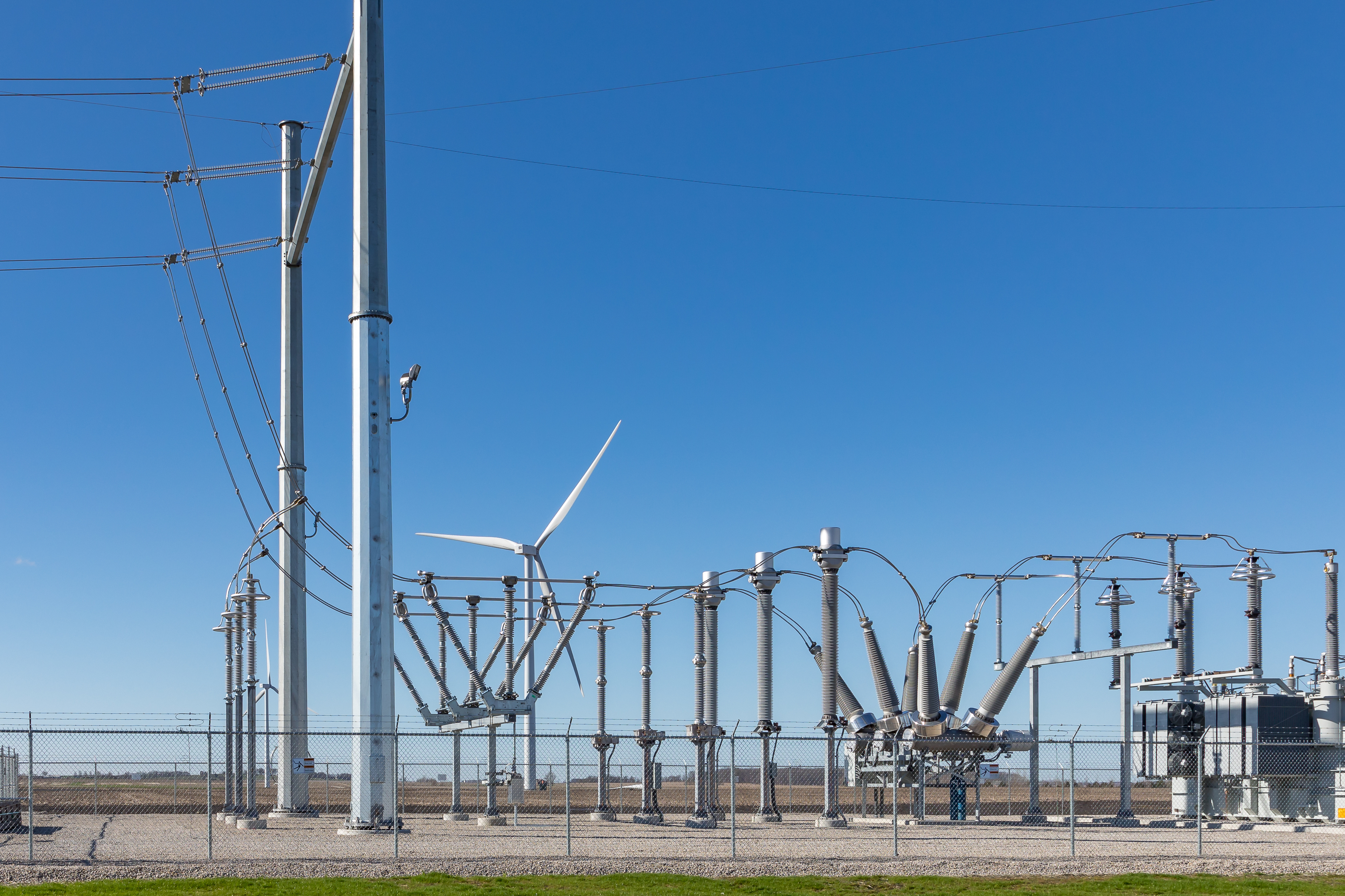
Of the above-ground equipment in the substation, the most visually striking structures are those that support and terminate the wires coming into and leaving the yard. These are loosely referred to as “high side” and “low side” lines based on the voltages they carry. A substation might have a 345 kV high side to receive power from a transmission line and several 25 kV lines on the low side feeding different local distribution lines. Some substations will also have multiple high-side feeds from different transmission lines, or may have multiple low-side inputs from wind or solar plants that the substation will combine into one or more high-side transmission lines.
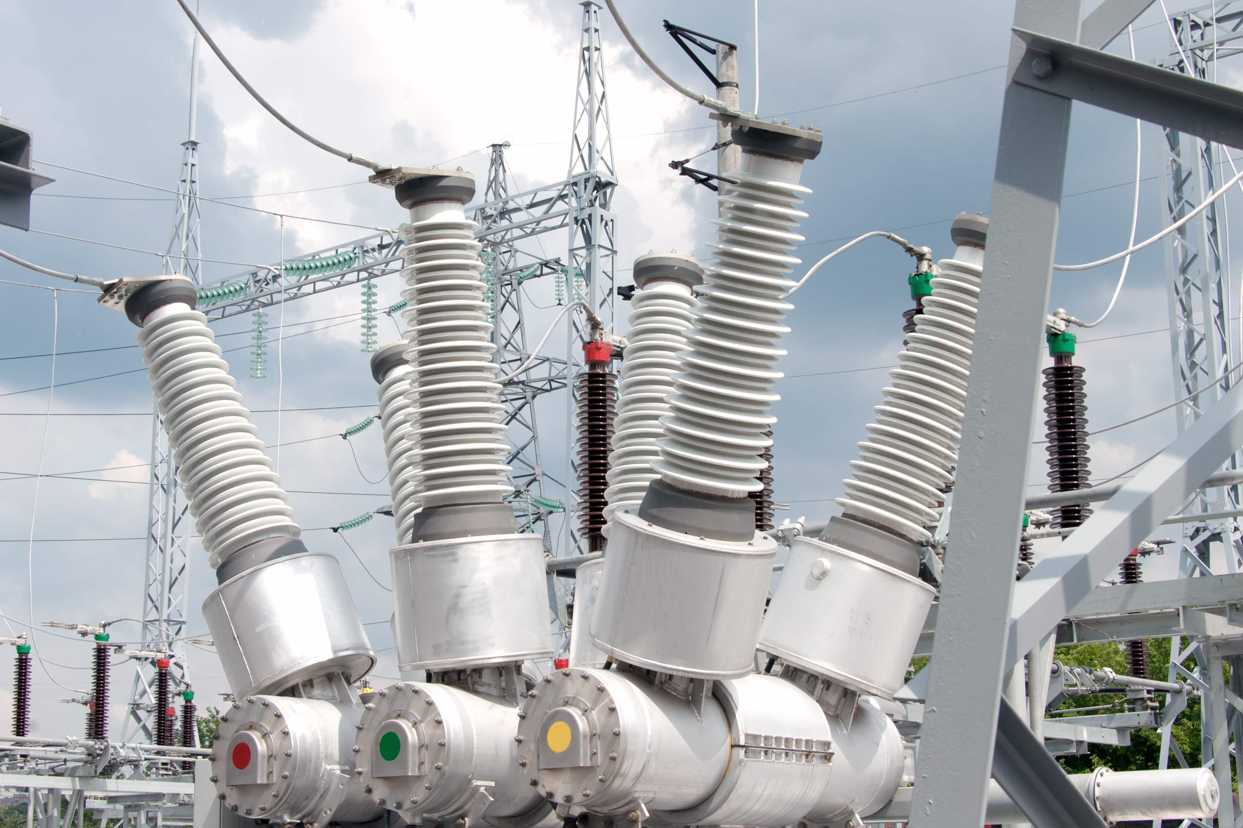
One way to tell the high-side and low-side lines apart is by the size of their insulating bushings. Bushings are used to electrically and physically separate conductors from enclosures and supports, and the longer the bushing, the higher the voltage. Bushings are made from ceramic, glass, or polymers, and generally have stacks of circular fins that reduce the possibility of electrical discharge from the line to something with a lower potential. The highest voltage bushings are often fitted with special corona caps, which are circular cages that reduce the possibility of corona discharges from the relatively sharp tip of the bushing.
Something that stands out about most substations is that there seem to be three copies of each piece of equipment. Each set of high-side lines comes into the substation in a set of three, there are often three transformers (or one transformer with three input bushings and three output bushings), and all of the gear between the input and the output seems to be in triplicate. This is thanks to the three-phase electrical system in North America. Electrical transmission and distribution systems are all three-phase power, and while residential customers rarely enjoy such service to the home, commercial and industrial installations almost universally have it.
While the high-side and low-side lines entering and leaving the substation are generally — but not always — overhead wires, inside the substation, most of the components are connected by a series of overhead busbars. Busbars are simply pieces of metal pipe, often galvanized steel or aluminum and usually in groups of three, which are attached to equipment bushings either directly or via jumper wires. Busbars have the advantage of not sagging or swaying in the wind, but do have a few disadvantages, too. When busbars get hot they expand, and since they’re rigid and supported firmly on each end they’ll either buckle or break their supports. That means busbars have to be provided with expansion joints.