
![3d-printering:-adaptive-bed-leveling-[hackaday]](https://i0.wp.com/upmytech.com/wp-content/uploads/2024/06/191878-3d-printering-adaptive-bed-leveling-hackaday-scaled.jpg?resize=800%2C445&ssl=1)
3D Printering: Adaptive Bed Leveling [Hackaday]

Have you ever read about something and thought, “Gee whiz! Why did I never think about that?” That was my reaction to reading about a feature commonly associated with Klipper called adaptive bed leveling or adaptive mesh leveling. Too bad I don’t typically use Klipper, but it all worked out, and I’ll show you how it might work for you.
What Is It?
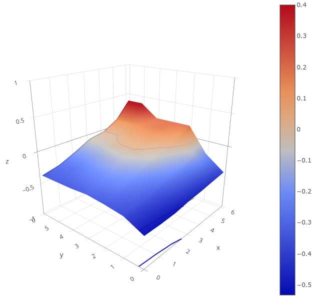
Once a luxury, most 3D printers now come with some kind of bed level sensor. The idea is that the printer can probe the bed to determine the shape of the build plate and then adjust the build plate accordingly. So if a particular spot on the bed is 0.5 mm too high, the nozzle can rise 0.5 mm when it is in that area. There are several techniques Marlin firmware uses, including what I usually use: UBL. Some people scan the bed once and hope it won’t change much. Others will do a time-consuming scan before each print.
However, adaptive bed leveling is a bit different. The idea is that the printer only probes the area where the part is going to print. If your print bed is 235 mm x 235 mm but your part is 50 mm square, you could just probe the points under the 50 mm square.
This does several things. For a given number of points, there is less motion, so it should be faster. Also, for the same number of points, you will have a much denser mesh and, thus, a better idea of what the bed is at any given point. You could even reduce the number of points based on the size of the part you are printing.
When you think about it, it is a dead simple idea. What’s not to love? For most print jobs, you’ll have less work for the printer, faster prints, and a denser mesh. But how do you do it?
How Do You Do It?
Can you make this work with your printer? Maybe. The trick is you need a way to tell your printer firmware to restrict the mesh area. You also need a way to have the slicer output a bounding box for the part, but that’s usually not hard. If you had to, you could even post process your Gcode and figure that out, but you probably won’t have to.
I
f you use linear or bilinear leveling, you are in business. That’s because the G29 command for bilinear accepts an L, R, F, and B parameter that lets you set the left, right, front, and back measurements of the probing grid. You can also set the number of probe points with H. Actually, H sets one side of the square, so if H=5, you will probe 25 points in the area.
However, I use UBL, and on one of my printers, I think I’m out of luck without changing something in the firmware. While there is a mesh inset setting, it is set when you build the firmware, so it won’t be practical to change it on the fly.
However, two of my printers are Ender 3 v2 Neo machines. By themselves, they use some odd variant of normal leveling, but I long ago flashed them with the excellent “professional” firmware by [mriscoc]. This is Marlin configured for these machines and — at least the version I use — has UBL set. But, there’s a catch.
The firmware has some custom Gcodes that start with C. C29 sets the mesh size and location very much like other versions. For some reason, it also sets the temperature. Here’s the documentation:
C29 Ln Rn Fn Bn Tn Nn Xn Ym : set probing mesh inset (Left, Right, Front, Back) in mm. T is the probing temperature (T0 doesn’t change the current bed temperature) and N is the density or amount of grid points NxN, it is posible to set a NxM density by using X and Y. In UBL use G29 S# to save to a mesh slot number #.
Try It!
Just as an experiment, I sent the following to the printer via a terminal:
C29 L100 R150 F100 B150 T0 N5
Nothing happened. But when I performed a G29 P1 to probe the bed, it obeyed the new restriction. All that was left was to make the slicer output the correct startup code. Of course, if you are using bilinear levelling, you’ll use G29 instead and have to change a few of the arguments.
Engage Start Up Sequence
Most slicers allow you to put placeholder variables in your Gcode scripts. You may have to look it up for your slicer. There are also plugins that can do the work, but you’d need to change their G29 to C29 (in my case). I mostly use SuperSlicer, which is forked from PrusaSlicer, which is forked from Slic3r.
Here’s part of my startup code:
G28 ; home all
C29 L{first_layer_print_min[0]} R{min(190,first_layer_print_
That’s it. If you have a line that purges your nozzle, you might want to correct it using similar logic or just add a few skirt loops in the slicer and forget about it. Note that I probe 25 points, which might be a bit much for a small part. It would be nice to write a script to detect how big a part is and adjust things. Note that Prusa has enough power to do this totally in the start code, but it would be different in Slic3r or Cura. If you look around, there are a few different examples of doing this for both slicers and various firmware that you will — no doubt — have to adapt to your circumstances.
I need to crack into the firmware for my other printer to see if a similar C command is feasible to add. But that’s for another day, especially since the C29 command is provided as object code only, so I’ll have to start from scratch. Luckily, I’m used to building (and rebuilding) Marlin for all the machines, especially that one, since it is a custom blend of many parts. I may switch out to bilinear leveling. Or, I could break down and go to Klipper, I suppose.
We want to try fast scanning next. Of course, things are simple if you tram your flat bed once and forget it. That is until something changes.